Table of Contents
Advertisement
Quick Links
Advertisement
Table of Contents

Related Manuals for Leica DSX


Summary of Contents for Leica DSX
- Page 1 Leica DSX User Manual Version 2.0 English...
- Page 2 Leica USB stick • https://myworld.leica-geosystems.com • Leica Geosystems On the last page of this manual, you can find the address of Leica Geosystems address book headquarters. For a list of regional contacts, please visit http://leica-geosystems.com/contact-us/sales_support. myWorld@Leica Geosystems offers a wide range of services, information and training material.
- Page 3 Description myProducts Add all products that you and your company own and explore your world of Leica Geosystems: View detailed information on your products and update your products with the latest software and keep up- to-date with the latest documentation.
-
Page 4: Table Of Contents
System Components Delivery Contents DSX Components Accessories General Battery Handling Requirements for Using a GNSS Antenna with the DSX Setup Unfolding and Adjusting the Handle Attaching and Connecting the Laptop or Tablet Inserting the Battery Mounting the Pole Support (Surveyor Kit Only) -
Page 5: Safety Directions
Safety Directions General Description The following directions enable the person responsible for the product, and the person who actually uses the equipment, to anticipate and avoid opera- tional hazards. The person responsible for the product must ensure that all users understand these directions and adhere to them. -
Page 6: Definition Of Use
Suitable for use in dry environments only and not under adverse conditions. Responsibilities Manufacturer of the Leica Geosystems AG, CH-9435 Heerbrugg, hereinafter referred to as Leica product Geosystems, is responsible for supplying the product, including the User Manual and original accessories, in a safe condition. -
Page 7: Hazards Of Use
To be familiar with local regulations relating to safety and accident pre- • vention To inform Leica Geosystems immediately if the product and the applica- • tion become unsafe To ensure that the national laws, regulations and conditions for the oper- •... - Page 8 WARNING Lightning strike If the product is used with accessories, for example masts, staffs, poles, you may increase the risk of being struck by lightning. Precautions: ▶ Do not use the product in a thunderstorm. WARNING Folding the handle Risk of crushing hands and fingers. Precautions: ▶...
- Page 9 Precautions: ▶ Do not open the product! ▶ Only Leica Geosystems authorised service centres are entitled to repair these products. For the AC/DC power supply and the battery charger: WARNING Electric shock due to use under wet and severe conditions If unit becomes wet it may cause you to receive an electric shock.
- Page 10 WARNING Inappropriate mechanical influences to batteries During the transport, shipping or disposal of batteries it is possible for inap- propriate mechanical influences to constitute a fire hazard. Precautions: ▶ Before shipping the product or disposing it, discharge the batteries by the product until they are flat.
- Page 11 Risk of injuries to users and equipment destruction due to lack of repair knowledge. Precautions: ▶ Only authorised Leica Geosystems Service Centres are entitled to repair these products. CAUTION Not properly secured accessories If the accessories used with the product are not properly secured and the product is subjected to mechanical shock, for example blows or falling, the product may be damaged or people can sustain injury.
-
Page 12: Electromagnetic Compatibility (Emc)
Precautions: ▶ Although the product meets the strict regulations and standards which are in force in this respect, Leica Geosystems cannot completely exclude the possibility that other equipment can be disturbed or that humans or animals can be affected. ▶... -
Page 13: Fcc Statement, Applicable In U
Although the product meets the strict regulations and standards which are in force in this respect, Leica Geosystems cannot completely exclude the possib- ility that function of the product may be disturbed in such an electromagnetic environment. - Page 14 CAUTION Changes or modifications Changes or modifications to this unit not expressly approved by the party responsible for compliance could void the user’s authority to operate the equipment. ▶ Do not change or modify this unit without approval by the party respons- ible for compliance! Operation of this device is restricted to law enforcement, fire and rescue offi- cials, scientific research institutes, commercial mining companies, and con-...
-
Page 15: Requirements Of Rss-220 For Ground Antennas (En/Fr), Applicable In Canada
Changes or modifications not expressly approved by Leica Geosystems for compliance could void the user's authority to operate the equipment. Labelling DSX The model and serial number of DSX are indicated on the model plate which can be found in the battery compartment. Model: DSX Art.No.:... - Page 16 CANADIAN REPRESENTATIVE Company Name : Leica Geosystems Ltd CN Number : 3177B Contact Name : Sudha Sachdeva City : SCARBOROUGH, Ontario M1W3S2 Telephone No : +1 416 497 2463 Email : sudha.sachdeva@leicaus.com Safety Directions...
-
Page 17: Description Of The System
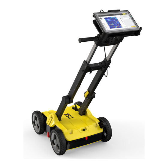
Description of the System General Area of application The DSX utility detection system is designed to detect and locate both metallic and non-metallic underground utilities. It provides georeferenced utility maps in survey-grade accuracy when a supported positioning system is used. -
Page 18: Dsx Components
DSX to ensure correct measurements even in rough terrain. Handle The handle of the DSX can be adjusted both in height and inclination. The recommended inclination is indic- ated with markers on the handle. For easy transport of the DSX, the handle can be folded up. -
Page 19: Accessories
The DSX battery is removable from the battery compartment and is ☞ chargeable. You cannot turn on the DSX while the battery compartment is empty. ☞ Place the battery in the charger and use the appropriate plug head before charging. -
Page 20: Requirements For Using A Gnss Antenna With The Dsx
Requirements for Using a GNSS Antenna with the DSX Requirements The DSX can be used with a GNSS antenna to position the radar-scanning data in an absolute coordinates system and to receive real-time positional correc- tions while the DSX cart is moving and collecting data. -
Page 21: Setup
Setup Procedure for setting The setup procedure of the DSX consists of the following steps: up the DSX Unfolding and adjusting the handle (refer to 3.1 Unfolding and Adjusting • Handle) Inserting the battery (refer to 3.3 Inserting the Battery) •... -
Page 22: Inserting The Battery
• Use the double socket arm to hold the two RAM balls: Adjust the tablet cradle until optimal inclination and then tighten the screw on the double socket arm. Plug in the DSX LAN cable to the tablet. 0019637_001 xxxxxx_001... -
Page 23: Mounting The Pole Support (Surveyor Kit Only)
Place the lower clamp in the housing bracket, and then fit the upper clamp in the handle bracket. Tighten the screw of the handle bracket. Switching the DSX ON/OFF Switch the DSX device ON/OFF 0019637_001 xxxxxx_001 xxxxxx_001 Press the ON/OFF key on the DSX. Setup... -
Page 24: Calibrating The Encoders
Ensure that the tablet is connected to the DSX. ☞ Turn on the DSX. Turn on the tablet and start the DXplore software. Start the calibration procedure with the DXplore software. Refer to Wheel encoder calibration. -
Page 25: Dxplore Software
DXplore Software Software Installation Requirements for When purchasing a DSX package that includes a CT1000 tablet, the DXplore installing the DXplore software is already installed on the tablet. software DXplore software can be downloaded from myWorld or updated through the "Update"... - Page 26 Wheel encoder calibration • Measure a 10‑meter linear distance precisely and push your DSX radar cart until reaching the exact 10‑meter Make sure the red markers on the side are aligned with the end point, then tap Distance is processed...
- Page 27 Run in full screen: Enables you to maximise the DXplore screen when • reopen DXplore next time. Analytics: Enables the user to allow analytics of data and automatic shar- • ing of project data, provided that an internet connection exists. Bottom buttons Button DSX inactive DXplore Software...
-
Page 28: Data Acquisition
Button DSX active Button DSX indicates the connection status to the DSX utility detection system. In active mode, the button should be green. Make sure, the button stays green throughout the entire data acquisition. ☞ Once the DSX detection system is turned on and the CT1000 tablet gets connected to the LAN cable, this but- ton should turn to active mode. - Page 29 These values indicate the cart position in the grid. Zoom to and center on grid. Show/hide the layers and grid lines. Indicates the connection status to the DSX utility detection system. This icon should be green throughout the entire acquisition. Refer Button DSX active for details.
- Page 30 Use Arrow buttons to move the cart position and change the ori- entation before a scan line starts. Acquisition While the DSX cart is moving, the orientation or position cannot be changed. The remaining distance of the scan line is displayed. DXplore Software...
- Page 31 Once the cart goes beyond the end point of the scan line, the remaining distance becomes a warn- ing. If exceeding a certain distance and if the Stop Scan button is not tapped, the software forces a stop to avoid distance calculation errors. Tap Start Scan before starting a new line.
- Page 32 When connected to a positioning device, the acquisition screen can ☞ be viewed in both 2D and 3D views. When the DSX is connected to a positioning device, a real-time posi- tion can be observed in the viewer area, as well as the scanned path.
- Page 33 Select a starting point for a mesurement line by touching a position on the screen. A menu promt will appear to select a second point. Select the second point for the distance meas- urement by touching the desired location on the screen.
- Page 34 Move the cart so that the pole is directly over the desired point. Press OK to set the first measurement point. Move the cart to the second point so that the antenna pole is dir- ectly over the desired end point of the meas- urement.
- Page 35 Circles are also displayed on the scan starting point, reflecting a radius of 10 cm (4"), 20 cm (8") and 50 cm (20"). The right-side view mode will close, as soon as the cart gets pulled away from the point where the red dot is set. In the acquisition screen, use the arrow buttons to position the...
-
Page 36: Data Processing
Data Processing Data processing Tap the button Analyse Data on the top right of the acquisition screen to screen open the processing/tomography screen. This button is greyed out when data acquisition has not been completed. It turns yellow once the acquisi- tion is completed. - Page 37 2D and 3D View button. 2D view is the top view from above and sees the • entire area in a flat view. 3D view allows rotation to view utilities in various • depths. Zoom to and centre on grid. Toggle this button for displaying the tomography in dif- ferent colour schemes.
- Page 38 Tap Export to save your project results: Export Detected Utilities: In DXF, DWG and SHP • format. Specify the export coordinate system. Export Tomography Image: In image formats. PNG, • JPG, TIFF, and so on. Generate Report: Generates a survey report. •...
- Page 39 Contrast slider for Use the contrast slider, placed at the left side of the processing screen, to viewing tomography adjust the contrast of the tomography for a more enhanced, or a more subtle, visualisation. GNSS/TPS scanning The acquisition line scan can be path in results screen viewed in the results screen under Layers icon.
- Page 40 ☞ For acquisition completed without GNSS/TPS, only the scanned path will be displayed as green arrows. Masking of grid edges ☞ Outer edges of the grid in results view, in order not to use them as a reference when a strong reflection is present in the masked area.
- Page 41 The control panel window offers the options of 10, 15, or 20 non-over- lapping tomography slices. The depth range of the tomography slices are automatically adjusted accordingly on the depth slider bar. ☞ Tomography configurations for each project are saved separately. Enhanced DXF/DWG Exported DXF/DWG files permit viewing of utilities and anomalies in 3D view file export...
-
Page 42: Project Management
Project Management Step-by-step The Project Management feature in DXplore provides users easy access pre- view, edit and open projects. Select Manage Projects on the bottom right of the DXplore Home screen. The Manage Projects screen provides a quick overview of all recently created or used DXplore projects along with their date and... -
Page 43: Planning A Survey
Planning a Survey Jobsite Investigation To carry out a survey with the DSX in the most efficient way, gather all avail- able information before each project: Make yourself familiar with the jobsite features. • Obtain technical maps, recommended in DXF format, about existing utilit- •... -
Page 44: Procedures For Working With The Dsx
Procedures for Working with the DSX Performing a Quick Scan Step-by-step The Quick Scan allows for a brief inspection of the desired site without per- forming a full scan. This procedure can be used as a means of guidance to quickly validate location of a particular utility and find optimal orientation to position the grid. - Page 45 Quick Scan area. ☞ Multiple line scans must be at least 50 cm (1’ 8”) apart but not more than 100 cm (3’ 3”). Procedures for Working with the DSX...
- Page 46 Quick Scan ‐ With Positioning Device Click on the Quick Scan icon displayed in the middle section of the Home Screen in DXplore. Procedures for Working with the DSX...
- Page 47 Measure distance by drawing Select the Draw Utility button on the screen to access the functional- ity. Procedures for Working with the DSX...
- Page 48 Google Maps layer Step-by-step Press the crop icon but- ton, on the left side of the Quick Scan screen to enable the cropping feature. Procedures for Working with the DSX...
-
Page 49: Preparing An Acquisition
DSX battery are fully charged. It is recommended to always have have a second fully charge DSX battery with you as a replacement. At the jobsite, set up the DSX and mount the accessories, if avail- able. Refer to Setup. - Page 50 Select Position using Google Maps or Posi- tion using a CAD layer or No positioning. ☞ As an example, Position using Google Maps is selected. Google Maps requires con- nection to the Internet. Procedures for Working with the DSX...
- Page 51 Select Next: Summary to continue. Confirm the information of the project summary. Save and close the draft for further scan or proceed to scanning by typing Go to Acquisi- tion. Procedures for Working with the DSX...
- Page 52 It is mandatory to ☞ check on each slice to find utilities in that depth range. Tap Add Utility and start marking the utility using your finger. Procedures for Working with the DSX...
- Page 53 If the utility is not found, there is still the option to keep it as an anomaly. View your utilities in Once all utilities are ☞ marked, continue with the export. Procedures for Working with the DSX...
- Page 54 Step-by-step Proceed with the con- nected positioning device or select an alternative workflow. Select the coordinate system and later optionally a CAD layer or proceed with WGS84 and Google Maps layer. Procedures for Working with the DSX...
- Page 55 The software utilizes a ☞ rectangular-shaped grid for the next stages. Therefore, a 90-degree angle should be defined as correctly as possible between the grid sides. Procedures for Working with the DSX...
-
Page 56: Mapping Utilities Using A Positioning System
GNSS antennas that provide various levels of GPS accuracy. Refer to 6.4.1 GNSS Antennas. In addition, the DSX can also be paired with Total Positioning Systems (TPS) to directly stream the coordinates of the DSX to DXplore. Refer to 6.4.2 TPS Sys- tems. - Page 57 The antenna models, that are not supported with a direct connection to DXplore (refer to the table) can be used with DXplore if they are compatible with the NMEA protocol and are listed in the table in the columns with the heading DXplore NMEA connection. Procedures for Working with the DSX...
- Page 58 (POI’s and detected utilities) in absolute heights. orthometric height DXplore supports the following geoid corrections: WGS84 ellipsoid height • Reference ellipsoid height • Orthometric height, if the geoid correction file of the region is available • and selected or imported Procedures for Working with the DSX...
-
Page 59: Gnss Antennas
Open DXplore software. Tap button Grid Scan to start a scan. Enter project informa- tion. Select Use GNSS antenna. Choose the antenna you wish to connect with, and tap Connect. Ensure the pole height is correct. Procedures for Working with the DSX... - Page 60 Do NOT check Skip ☞ antenna configura- tion, and press Next button for such anten- nas, to make your selection. Once connected, select Continue with. Review Check GNSS Status and tap Use GNSS antenna to con- tinue. Procedures for Working with the DSX...
- Page 61 The point turns green once set. Move the cart to set the third point for the scan area. Tap OK to set the third point for the scan area. The point turns green once set. Procedures for Working with the DSX...
- Page 62 Go to Acquisi- tion. Scan Make sure to have the DSX works using grid principle relaying on grid physically marked scanning the ground in both parallel lines on the ground surface. at 50 cm/18 in intervals in transversal Refer to setup tutorial.
- Page 63 Tap Add Utility and start marking the utility using your finger. DXplore then verifies it. ☞ Utility Detected: If available, make sure to enter the information correctly. ☞ The software estimates the depth. Procedures for Working with the DSX...
- Page 64 View your utilities in Once all utilities are ☞ marked, continue with the export of the project output. Export the project output Make sure all utilities are marked Tap on Export to export the project out- Procedures for Working with the DSX...
- Page 65 Tap Detect to get the paired antenna to the list. Enter the correct pole height. ☞ Do not consider the bottom shift from the pole tip above ground. Tap Connect once the antenna was found. Procedures for Working with the DSX...
- Page 66 Tap Use ‖ once satisfied with the accur- acy. ☞ If the accuracy is not high enough, tap Disable ‖. The Home screen appears with the GNSS icon in green. Procedures for Working with the DSX...
- Page 67 To define the grid ori- entation, walk to the second point (upper left corner of the grid) and lock it as previously. In real time, a label is displayed to reflect the size of the grid side. Procedures for Working with the DSX...
- Page 68 PNG images for all tomography depth slices, along with the CAD file. A dedicated folder is automatically created on the designated des- tination where both the CAD file and the PNG images will be stored. Procedures for Working with the DSX...
-
Page 69: Tps Systems
DSX pole mount. Pair with the TPS. Have the TPS measur- ing, already before con- necting to it in DXplore. Open DXplore. Tap button Grid Scan to start a scan. Procedures for Working with the DSX... - Page 70 Continue with. Review Check TPS Status and tap Use TPS to continue. You have the option to add a CAD Layer at this time. Then you can move to the grid defini- tion screen. Procedures for Working with the DSX...
- Page 71 The point turns green once set. Ensure the distance the ☞ cart is moved is incre- mental in distances of 50 cm (18 inches) and angle with first side is Procedures for Working with the DSX...
- Page 72 Project setup and grid Select the positioning definition workflow device. Step-by-step Proceed with the con- nected positioning device or select an alternative workflow. Procedures for Working with the DSX...
- Page 73 To define the grid size, walk to the third point and lock it as previ- ously. A label is dis- played in real time indicating the corner angle. Procedures for Working with the DSX...
- Page 74 This can be done by accessing the File references menu of the CAD software and then change the path type of each PNG image to Absolute. The tomography images will be loaded and displayed in the CAD soft- ware normally. Procedures for Working with the DSX...
-
Page 75: Care And Transport
Transport Shipping When transporting the product by rail, air or sea, always use the complete ori- ginal Leica Geosystems packaging, container and cardboard box, or its equival- ent, to protect against shock and vibration. Shipping, transport of When transporting or shipping batteries, the person responsible for the... - Page 76 Connectors with dust Wet connectors must be dry before attaching the dust cap. caps Care and Transport...
-
Page 77: Technical Data
= 99.84 MHz; f = 2008.00 MHz) Maximum measured e. −53.43 dBm r. p. in air Antenna orientation Broadside antenna array in the direction which is perpendicular to the DSX moving direction Sampling frequency 400 kHz Battery for DSX Type Li-Ion Voltage 14.8 V... -
Page 78: Conformity To European Regulations
Directive 2014/53/EU. The full Declaration of Conformity can be found either on the storage device or or on the following website: https://leica-geosystems.com/about-us/compliance-standards/ conformity-declarations This is a Class A product. In a domestic environment it may •... - Page 79 Warning: this equipment is destined for use in industrial environments (Class A apparatus). In residential, commercial and light industry environments, this apparatus may generate radio interference: in this case, the user may be required to operate while taking appropriate countermeasures. The apparatus is sensitive to the presence of external electromagnetic fields, which may reduce its performance.
-
Page 80: Software Licence Agreement/Warranty
Rights, Limitation of Liability, Exclusion of other Assurances, Governing Law and Place of Jurisdiction. Please make sure, that at any time you fully comply with the terms and conditions of the Leica Geosystems Software Licence Agreement. Such agreement is provided together with all products and can also be referred to and downloaded at the Leica Geosystems home page at http://leica-geosystems.com/about-us/compliance-standards/legal-documents... - Page 82 900644-2.0.0en Original text (900644en-2.0.0) Published in Switzerland, © 2021 Leica Geosystems AG Leica Geosystems AG Heinrich-Wild-Strasse 9435 Heerbrugg Switzerland www.leica-geosystems.com...
Need help?
Do you have a question about the DSX and is the answer not in the manual?
Questions and answers