Table of Contents
Advertisement
Quick Links
Advertisement
Table of Contents

Related Manuals for Eaton XP-504


Summary of Contents for Eaton XP-504
- Page 1 08/2021 MN048028EN Manual XP-504 manual...
-
Page 2: Company Information
No part of this manual may be reproduced, stored in a retrieval system, or transmitted in any form or by any means, whether electronic, mechanical, photocopying, micro-filming, record- ing, or otherwise, without the prior written permission of Eaton Industries GmbH, Bonn. Subject to alteration. -
Page 3: Before Starting With The Installation
DANGER! Hazardous electrical voltage! Before starting with the installation Installation requires qualified electrician desktop devices and portable devices only when the housing is closed. Disconnect the power supply of the device. Measures should be taken to ensure the proper Secure against retriggering restarting of programs interrupted after a voltage Verify isolation from the supply dip or outage. -
Page 5: Table Of Contents
0.1.5.2 Additional user information 0.1.5.3 Links Description Use as intended Device models 1.2.1 PC features – features on all XP-504 PCs 1.2.2 Terminal features – features on all XP-504 terminals 1.2.3 Device variants 1.2.3.1 Operating system on XP-504 PCs 1.2.3.2... - Page 6 3.5.1.1 Functional earthing Panel PC 3.5.1.2 Power supply Using peripheral devices - External connections Layout of interfaces SD card USB interfaces Ethernet Display interfaces 4.5.1 DisplayPort (DP) 4.5.2 High Definition Multimedia Interface (HDMI) RS-232/RS-422/RS-485 serial ports XP-504 08/2021 MN048028EN Eaton.com...
- Page 7 Dedicated features 7.2.3.1 Protect Mode (Operated with two drives, C:\ and D:\) 7.2.3.2 Protect-Mode data organization 7.2.4 Managing users and configuring the XP-504 7.2.5 Modifying an Account Name or Password 7.2.6 Device start without user login dialog box 7.2.7 License Eaton Galileo-Open Runtime 7.2.8...
- Page 8 Data sheet A.1.2 Dimension and weight specifications A.1.2.1 XP-504-10-... Front mounting A.1.2.2 XP-504-15-... Front mounting A.1.2.3 XP-504-21-... Front mounting A.1.3 General data A.1.4 Information on the power supply A.1.5 Approvals and declarations Further usage information Alphabetical index XP-504 08/2021 MN048028EN Eaton.com...
-
Page 9: About This Documentation
0.1 About this documentation 0.1 About this documentation This manual contains all the information you will need in order to use the XP-504 safely and effectively. The manual XP-504 manual is considered an integral part of the device and must always be readily available in the device's close proximity so that users have access to it. -
Page 10: Target Group
Installation requires qualified electrician Follow the safety instructions for the XP-504! The section on safety instructions must be read and understood by everyone who will be working with the XP-504 before the actual work is performed HMI. WARNING Incomplete operator manual copies... -
Page 11: Legal Disclaimer
Do not use the XP-504 before reading and understanding this manual. Hazards posed by the XP-504 cannot be eliminated if the safety instructions are not observed – especially if the XP-504 is installed and commissioned by unqualified per- sonnel and/or is used improperly. -
Page 12: Writing Conventions
Dangerous Electrical Voltage! CAUTION Warns of the possibility of hazardous situations that can cause injury. Property damage warning CAUTION Warns about the possibility of material damage. Prohibited uses, actions, etc. Explains the prohibition Explains the instruction XP-504 08/2021 MN048028EN Eaton.com... -
Page 13: Additional User Information
Publication title For identifying the Eaton publication code External Internet addresses. The corresponding pages will be opened in a separate browser window when you click on the icon.They will be shown after the icon. - Page 14 0.1 About this documentation XP-504 08/2021 MN048028EN Eaton.com...
-
Page 15: Description
1. Description XP-504 devices are used as control and monitoring devices. XP-504 devices are the answer to the growing demand of machine and system man- ufacturers for high-precision, cost-effective HMI solutions with industrial-grade capacitive multi-touch technology. Accordingly, the XP-504 series offers widescreen terminals with sizes of 10.1", 15.6", and 21.5". -
Page 16: Use As Intended
Any other use must be discussed and agreed upon with the manufacturer in advance. The XP-504 must be used only in locations for which this series of devices is approved. Make sure to read and follow the information and labels on the nameplate for the XP-504, as well as section Approvals and declarations in the appendix. -
Page 17: Terminal Features - Features On All Xp-504 Terminals
1. Description 1.2 Device models 1.2.2 Terminal features – features on all XP-504 terminals Every terminal features a widescreen color display, TFT. In addition, every terminal can be used with gestures (multi-touch touch panel). In order for this functionality to work properly, you must press on the Projected Capacitive Touch (PCT) with a finger or stylus. -
Page 18: Nameplate
Type approval and certification marks and information Layout of ports/interfaces and controls To get fast and effective support, make sure to always provide Customer Service with the following information from the nameplate: Article No. (part No. or article No.) Serial No. XP-504 08/2021 MN048028EN Eaton.com... -
Page 19: What The Different Parts Of The Part Number Mean
1.5 What the different parts of the part number mean The Part number includes information that specifies the version and model of the spe- cific device being used. The Part number can be found at the type plate of the XP-504. 1.5.1 Panel PC Tabel 1: Part number XP-504 - .. -
Page 20: Support
1. Description 1.7 Support Order accessories through your supplier or through the Eaton online catalog Eaton.com/ecat 1.7 Support To get fast and effective support, make sure to provide Customer Service with the fol- lowing information from the nameplate: Part-No. Serial-No For service and support, please contact your local sales team. -
Page 21: Conditions For Underwriters Laboratories Inc. (Ul) Listing
The torque used to tighten the screw terminals on the plug-in connection for the sup- ply voltage must not exceed 0.075 ... 0.79 Nm. 1.9 Marine approvals An application for approval for the XP-504 has been submitted to Det Norske Veritas. XP-504 08/2021 MN048028EN Eaton.com... -
Page 22: Safety Regulations
Do not run any XP-504 device unless it is in perfect technical condition. Make sure to always operate it as specified in this document and as intended. -
Page 23: Device Documentation
2.2 Mandatory requirements, personnel requirements 2.2.3 Device documentation This manual is considered an integral part of the XP-504 and must always be readily available in the device's close proximity so that users have access to it. Make sure that every person who will be working with the XP-504, regardless of the lifecycle stage involved, has read and understood the relevant parts of the doc- umentation for the XP-504. -
Page 24: Prerequisites For Proper Operation
2.2 Mandatory requirements, personnel requirements 2.2.5 Prerequisites for proper operation In order for XP-504 devices to be able to meet the contractually stipulated terms, the following must be observed: Only qualified personnel should be allowed to work with the XP-504. -
Page 25: Device-Specific Hazards
The lithium battery inside the XP-504 may explode if handled incor- rectly. Dispose of the XP-504 unit professionally. CAUTION DESTRUCTION The XP-504 should only be opened by the manufacturer or by an authorized center. Operate the device until only with the enclosure fully closed and sealed. CAUTION ELECTROSTATIC DISCHARGE Do not touch components (e.g., connector pins) that are elec-... - Page 26 Wire cross-sectional area ≧ 6 mm², length ≦ 350 mm, wide ≥ 20 mm The XP-504 needs to be connected to the conductive structure in, e.g., the control panel using the central earth point. This method of earthing is mandatory required for proper function.
- Page 27 CAUTION UV LIGHT Plastics will become brittle when exposed to UV light. This artificial aging will reduce the XP-504 unit's lifespan. Protect the XP-504 unit from direct sunlight and other sources of UV radiation. XP-504 08/2021 MN048028EN Eaton.com...
- Page 28 Do not use any pointy or sharp objects (e.g., knives). Do not use aggressive or abrasive cleaning products or solvents. Make sure that no liquids get into the XP-504 unit (short-circuit haz- ard) and that the XP-504 unit is not damaged in any way.
- Page 29 Protect the RJ45 plug-in connection from tensile forces at the socket. WARNING XP-504 units are products designed for use in industrial envir- onments as defined in ICE/EN 6100−6-4. These products can cause radio interference in domestic environments. In this case, the party operating the products must implement appropriate radio inter- ference suppression measures.
-
Page 30: Installation
Do not touch components (e.g., connector pins) that are elec- trostatic-sensitive. Discharge any static electricity from your body before touching the XP-504 (e.g., by touching an earthed metal object). Electrostatic discharges may damage or ruin assembly parts. Because of this, it is necessary to take precautions whenever hand- ling the XP-504 cards. -
Page 31: Installation Position
The size of the installation cutout depends on the device type: XP-504-10-...: e = 256 mm (10.07") ±0.5 (0.02"), f = 175 mm (6.88") ±0.5 (0.02") XP-504-15-...: e = 388 mm (15.28") ±0,5 (0.02"), f = 239 mm (9.40") ±0,5 (0.02") XP-504-21-...: e = 519 mm (20.43") ±0,5 (0.02"), f = 313 mm (12.32") ±0,5 (0.02") - Page 32 UV LIGHT Plastics will become brittle when exposed to UV light. This artificial aging will reduce the XP-504 unit's lifespan. Protect the XP-504 unit from direct sunlight and other sources of UV radiation. Make sure that the XP-504 does not overheat.
-
Page 33: Temperatures
Do not block the ventilation openings when mounting the XP-504: They are designed to allow air to circulate in order to cool the device. The XP-504 uses natural convection-based passive cooling, i.e., it does not use fans. The heat from the CPU and the power semiconductors in the power supply unit is brought together through a heat spreader and then dispersed into the surrounding air through the cooling fins on the housing. - Page 34 The panel builder is responsible for the temperature rise calculation. Eaton will provide heat dissipation data as necessary for design verification in conformity with IEC EN 61439 – please refer to the data sheet for the XP-504 in the online catalog at Eaton.com/ecat.
-
Page 35: Technical Conditions For Acceptance By Underwriters Laboratories Inc. (Ul)
3.2 Technical conditions for acceptance by Underwriters Laboratories Inc. (UL) The following conditions must be met in order for the certification of UL 61010-2-201 as per XP-504 to apply: Do not exceed a mounting position range between 45° towards the back and 10°... -
Page 36: Unpacking And Checking The Equipment Supplied
The HMI is sturdily built, but the components inside it are sensitive to excessively strong vibrations and/or mechanical shock. Accordingly, make sure to protect the XP-504 from mechanical loads that exceed the scope of the unit's intended use. The device should only be transported in its original packaging after being packed properly. -
Page 37: Mounting
List of tools: Wrench for Allen key: 2 mm (5/64") PZ2 Pozidriv screwdriver Open-ended wrench SW10 ground straps: Length ≤ 35 cm, width ≥ 20 cm with eyelet Torque wrench with Newton meter scale XP-504 08/2021 MN048028EN Eaton.com... -
Page 38: Preparations
Make sure that all the requirements for the installation location are met → page 32. 2. Make a cutout with the right size for the XP-504 at the location you selected. 3. Make sure that the mounting cutout has the right size. - Page 39 On the left and right sides of the device: One holding bracket each at the center fixing position Figure 8: Location of holding brackets for IP65 on XP-504-10-... XP-504-15-... Locations for ten holding brackets for an IP65 degree of protection...
- Page 40 On the left and right sides of the device: One holding bracket each at the upper and lower fixing positions Figure 10: Location of holding brackets for IP65 on XP-504-21-... IP rating If the gasket is resting in the correct position and the holding brackets are installed...
-
Page 41: Installing The Panel Pc
3.4 Mounting 3.4.2 Installing the Panel PC 1. Insert the XP-504 into the mounting cutout from the front. Figure 11: Mounting in the installation cutout 2. As long as the device has not been secured with all holding brackets, make sure to secure it so that it will not fall down. -
Page 42: Preparing The Device For Operation
Wire cross-sectional area ≧ 6 mm², length ≦ 350 mm, wide ≥ 20 mm The XP-504 needs to be connected to the conductive structure in, e.g., the control panel using the central earth point. This method of earthing is mandatory required for proper function. -
Page 43: E Lectrical Connection
38.4 W XP-504-15-..., max. 43.2 W XP-504-21-... max. 48.0 W Fuse Yes (fuse not accessible) Electrical current 10.1" (25.65 cm) 15.6" (39.6 cm) dis- 21.5" (54.6 cm) display display play 1.6 A 1.8 A 2.0 A XP-504 08/2021 MN048028EN Eaton.com... -
Page 44: Functional Earthing Panel Pc
Wire cross-sectional area ≧ 6 mm², length ≦ 350 mm, wide ≥ 20 mm The XP-504 needs to be connected to the conductive structure in, e.g., the control panel using the central earth point. This method of earthing is mandatory required for proper function. - Page 45 External diameter ≦ 11 mm Cable length ≦ 350 mm Tightening torque 1.3 Nm (11.5 lb-in) for the M6 nut Functional earth +24 V DC Figure 14: Screwing the functional earth conductor/ground strap onto the enclosure XP-504 08/2021 MN048028EN Eaton.com...
-
Page 46: Power Supply
+24 V DC = 24 V DC (18 - 36 V DC SELV) = ... 0.56 - 0.79 Nm (5 - 7 lb-in) 0 V +24 V DC Figure 15: Connecting the screw terminals on the XP-504 XP-504 08/2021 MN048028EN Eaton.com... - Page 47 Connect the power supply cable to a 24 VDC power supply that meets the requirements for safety extra-low voltages (SELV) set forth in IEC/UL 61010-2- 201. The XP-504 is now ready to run on 24 VDC. XP-504 08/2021 MN048028EN Eaton.com...
-
Page 48: Using Peripheral Devices - External Connections
4. Using peripheral devices - External connections 4. Using peripheral devices - External connections With its ports, Eaton's HMI makes it possible to connect a variety of peripheral devices and components. DANGER STRAY CURRENTS Large equalizing currents between the functional earthing system and the ground system of different devices may result in fire or in mal- functions due to signal interference. -
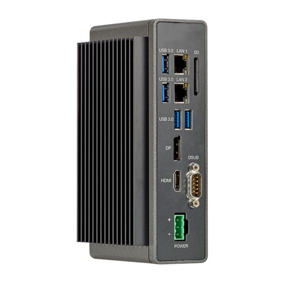
Page 49: Layout Of Interfaces
USB-Host 3.0 Dual-USB3.0 / 2.0 T, plug type A ⑧ Default display interface ⑨ HDMI Default display interface 1.4b ⑩ RS232/422/485 SUB-D plug 9-pole, not galvanically isolated configurable in BIOS; default setting: RS 232 full duplex XP-504 08/2021 MN048028EN Eaton.com... -
Page 50: Sd Card
If the SD card is being written to and a voltage drop occurs or the card is removed, data may be lost or the SD card may be ruined. Insert the SD card only when the XP-504 is de-energized. Avoid writing to SD cards. Reasons: SD cards have a limited number of write cycles. - Page 51 4. Using peripheral devices - External connections 4.2 SD card Figure 17: Remove SD card XP-504 08/2021 MN048028EN Eaton.com...
-
Page 52: Usb Interfaces
The HMI must be de-energized before connecting or dis- connecting any connections to it. Only use standard USB cables with a shield. Max. cable length: 5 m. Dual-USB 3.0/2.0 Type A USB 3.0/2.0 Type A Figure 18: USB connections XP-504 08/2021 MN048028EN Eaton.com... - Page 53 SSTX- Super Speed Transmitter SSTX- Super Speed Transmitter (UP) data cable USB 3.0 (DOWN data cable USB 3.0 SSTX+ Super Speed Transmitter SSTX+ Super Speed Transmitter (UP) data cable USB 3.0 (DOWN data cable USB 3.0 XP-504 08/2021 MN048028EN Eaton.com...
-
Page 54: Ethernet
8 7 6 5 4 3 2 1 Figure 21: LAN connections The XP-504 is to be connected only to internal Ethernet networks without exiting a facility and being subjected to TNVs. When the green LED lights up, this means that an active network has been detected and a LINK (2) to it has been established. -
Page 55: Display Interfaces
Figure 23: Pin assignment HDMI TMDS DATA2+ 11 TMDS CLK- TMDS DATA2- 13 n.c. TMDS DATA1+ 14 n.c. DDC CLK TMDS DATA1- 16 DDC DATA TMDS DATA0+ 17 DDC DATA TMDS DATA0- 19 TMDS CLK+ Hot plug Detect XP-504 08/2021 MN048028EN Eaton.com... -
Page 56: Rs-232/Rs-422/Rs-485 Serial Ports
Request to Send Clear To Send Ring Indicator Tabel 11: Pin assignment (RS422 mode) Signal RS422 TX- RS422 TX+ RS422 RX+ RS422 RX- n.c. n.c. n.c. n.c. The BIOS will need to be set to RS422 mode. XP-504 08/2021 MN048028EN Eaton.com... - Page 57 4. Using peripheral devices - External connections 4.6 RS-232/RS-422/RS-485 serial ports Tabel 12: Pin assignment (RS485 mode) Signal RS485 Data+ RS485 Data- n.c. n.c. n.c. n.c. n.c. n.c. The BIOS will need to be set to RS485 mode. XP-504 08/2021 MN048028EN Eaton.com...
- Page 58 4. Using peripheral devices - External connections 4.6 RS-232/RS-422/RS-485 serial ports XP-504 08/2021 MN048028EN Eaton.com...
-
Page 59: Commissioning
5. Commissioning 5. Commissioning When the device series XP-504 is used as intended, it will often be installed in a machine or system to function as controls and will be wired accordingly. In this case, the devices will need to be switched on and off using the corresponding machine controller. -
Page 60: Initial Commissioning
Display An external display unit (various display types) can be connected to the display ports (DP or HDMI). Ethernet The XP-504 can be connected to various computer networks using the two RJ-45 ports that serve network as Ethernet ports. Ethernet is a standard used for local networks, and requires twisted-pair cables in order to connect the computers. - Page 61 5.2 Running the XP-504 5.2 Running the XP-504 Once the XP-504 has been initially commissioned, it will run whenever it is connected to the power supply. In other words, it does not have to be separately switched on and off.
-
Page 62: Running The Xp-504
5. Commissioning 5.2 Running the XP-504 XP-504 08/2021 MN048028EN Eaton.com... -
Page 63: Operation
6. Operation 6.1 Safety instructions 6. Operation 6.1 Safety instructions Using XP-504 terminals entails additional risks associated with using the multi-touch function Observe the following instructions in order to keep you and others safe and avoid property damage. WARNING MALFUNCTIONS WHEN USING A TOUCH PANEL WITH MULTI-... - Page 64 Scratches and other damage on the device's glass panel may trigger unexpected operator actions. When functions are triggered incor- rectly in the system, bodily injury and property damage may occur. Make sure that the glass panel is not damaged during installation or use. XP-504 08/2021 MN048028EN Eaton.com...
-
Page 65: Handling Terminal
The XP-504 features a touch display with multi-touch capabilities. It is controlled by means of touching, inching, and gestures, all of which require the operator to touch the terminal with their fingertips. - Page 66 6. Operation 6.2 Handling terminal XP-504 08/2021 MN048028EN Eaton.com...
-
Page 67: Operating System
ONLY BE TRIGGERED BY USING MULTIPLE FINGERS AT THE SAME TIME Important operating functions must be programmed in such a way that they can only be triggered by gestures requiring multiple fingers on the touch panel at the same time. XP-504 08/2021 MN048028EN Eaton.com... - Page 68 If there is static contact on the touch panel during booting, this may result in functional restrictions. To prevent this, take the measures below: Do not touch the touch panel during booting! If you do touch it, make sure to move your finger(s) slightly! XP-504 08/2021 MN048028EN Eaton.com...
-
Page 69: Windows 10 Enterprise Ltsc
The Microsoft® Windows 10 Enterprise LTSC operating system comes pre-installed on XP-504 devices with part No. XP-504-..-…-…-2B or XP-504-..-…-…-2V. If your XP-504 is not a standard device or XP-504 is operated with a different oper- ating system these operating system specific descriptions may or may not apply to your device. -
Page 70: Protect-Mode Data Organization
Protect Mode. To do this, go to "Start → Eaton → Protect Mode Manager" in Windows, select the "Advanced" tab, and click on the "Enable Protect Mode" button. The system will then restart and return the XP-504 device to its normal protected state. -
Page 71: Managing Users And Configuring The Xp-504
Windows shutdown mechanism to prevent potential corruption of the operating system. It is recommended that the XP-504 unit be removed from any plant network while Pro- tect Mode is disabled and that all media used for software installation to be con- nected to the unit are scanned for malware prior to attachment. -
Page 72: Modifying An Account Name Or Password
You can change the "XP504" username and create other users in the Windows Con- trol Panel ("Start → Windows System → Control Panel → User Accounts"). If you have made changes and you have configured the XP-504 for starting auto- matically without a login, please update the corresponding settings in the Windows Registry. -
Page 73: Enabling / Disabling Iis Communication For Visual Designer
Visual Designer functions (e.g., remote project setup and WEB visualization). There are two applications for enabling and disabling this service (and the cor- responding TCP/UDP ports) that can be accessed by clicking on "Start → Eaton" in Windows: Activate IIS.cmd Deactivate IIS.cmd... - Page 74 7. Operating system 7.2 Windows 10 Enterprise LTSC XP-504 08/2021 MN048028EN Eaton.com...
-
Page 75: Faults
8. Faults 8. Faults This section provides troubleshooting information for your XP-504 in case it does not behave as expected. Fault Cause Remedy Check the power cord and Panel PC will not boot up No 24 VDC power supply power supply... - Page 76 8. Faults XP-504 08/2021 MN048028EN Eaton.com...
-
Page 77: Maintenance
Do not use any pointy or sharp objects (e.g., knives). Do not use aggressive or abrasive cleaning products or solvents. Make sure that no liquids get into the XP-504 unit (short-circuit haz- ard) and that the XP-504 unit is not damaged in any way. - Page 78 To get to the battery, pull out the battery holder. Remove the battery from the battery holder (red arrow) and insert the new bat- tery into the holder with the + terminal in front. Slide the battery holder back into its slot. XP-504 08/2021 MN048028EN Eaton.com...
-
Page 79: Repairs
For repairs, please contact your vendor or Eaton's Technical Support. CAUTION DESTRUCTION The XP-504 should only be opened by the manufacturer or by an authorized center. Operate the device until only with the enclosure fully closed and sealed. Use the original packaging to ship the device. -
Page 80: Storage, Transport And Disposal
Do not expose the device to direct thermal radiation from heating appliances. The ambient conditions must be met when transporting and storing the XP-504. The ambient air temperature for storage and transportation must not exceed the max- imum specified limit of: -20 –... - Page 81 The HMI is sturdily built, but the components inside it are sensitive to excessively strong vibrations and/or mechanical shock. Accordingly, make sure to protect the XP-504 from mechanical loads that exceed the scope of the unit's intended use. The device should only be transported in its original packaging after being packed properly.
-
Page 82: Disposal
Tempered glass across the entire surface (ESG) tempered soda-lime glass Non-glare surface (chemically microetched); gloss: 85 Designer bezel with direct-to-glass printing RAL 9005 jet black 3 mm thick (XP-504-10-...) 3 mm thick (XP-504-15-...) 4 mm thick (XP-504-21-...) computer core enclos- Galvanized steel, 1 mm thick and... -
Page 83: Appendix
Appendix Appendix A.1 Technical data A.1.1 Data sheet A.1.2 Dimension and weight specifications A.1.3 General data A.1.4 Information on the power supply A.1.5 Approvals and declarations A.2 Further usage information XP-504 08/2021 MN048028EN Eaton.com... -
Page 84: Technical Data
Appendix A.1 Technical data A.1 Technical data A.1.1 Data sheet The current specifications can be found in the data sheet for the device in the Eaton online catalog. Eaton.com/ecat Catalog No. Type Panel PC 199996 XP-504-10-A10-A01-2B 199997 XP-504-10-A10-A01-2V 199998 XP-504-15-A10-A01-2B... -
Page 85: Dimension And Weight Specifications
Appendix A.1 Technical data A.1.2 Dimension and weight specifications A.1.2.1 XP-504-10-... Front mounting ⏚ 58 mm 199.4 mm (7.85") 9 mm (0.35") (2.28") 254 mm (10") 89 mm 280 mm (11.02") (3.5") Figure 27: Dimensions for 10.1" (25.65 cm) front mounting devices in mm (inches) Width x Height x Depth 280 mm x 201 mm x 89 mm (11.02"... -
Page 86: Xp-504-15
Appendix A.1 Technical data A.1.2.2 XP-504-15-... Front mounting ⏚ 58 mm 199.4 mm (7.85") 9 mm (0.35") (2.28") 384.8 mm (15.15") 89 mm 412 mm (16.22") (3.5") Figure 28: Dimensions for 15.6" (39.6 cm) front mounting devices in mm (inches) Width x Height x Depth 412 mm x 238 mm x 89 mm (16.22"... -
Page 87: Xp-504-21
Appendix A.1 Technical data A.1.2.3 XP-504-21-... Front mounting ⏚ 58 mm 199.4 mm (7.85") 9 mm (0.35") (2.28") 518 mm (20.39") 89 mm 544 mm (21.42") (3.5") Figure 29: Dimensions for 21.5" (54.6 cm) front mounting devices in mm (inches) Width x Height x Depth 544 mm x 336 mm x 89 mm (21.42"... -
Page 88: General Data
Appendix A.1 Technical data A.1.3 General data The following specifications apply to all XP-504 units or to the specified part nos. where applicable. Ambient climatic conditions Air pressure (in operation) 795 - 1080 hPa max. 2000 m above sea level... - Page 89 USB-Host 3.0 Dual-USB3.0 / 2.0 T, plug type A SUB-D plug 9-pole, UNC nuts for interlocking, not galvanically isolated RS232/422/485 configurable in BIOS; default setting: RS 232 full duplex Default display interface HDMI Default display interface 1.4b XP-504 08/2021 MN048028EN Eaton.com...
- Page 90 XP-504-21-... Normally 350 cd/m2 Backlight dimmable via software Lifespan of backlight Normally 50000 h at 25 °C Format XP-504-10-... 16:10 XP-504-15-... 16:9 XP-504-21-... 16:9 Viewing range [left/right/above/below] XP-504-10-... normally 85°/85°/85°/85° XP-504-15-... normally 85°/85°/80°/80° XP-504-21-... normally 89°/89°/89°/89° XP-504 08/2021 MN048028EN Eaton.com...
-
Page 91: Information On The Power Supply
The applied voltage must meet the requirements for safety extra- low voltages (SELV) set forth in IEC/UL 61010-2-201. Electrical current 10.1" (25.65 cm) 15.6" (39.6 cm) dis- 21.5" (54.6 cm) display display play 1.6 A 1.8 A 2.0 A XP-504 08/2021 MN048028EN Eaton.com... -
Page 92: Approvals And Declarations
A.1 Technical data A.1.5 Approvals and declarations The following specifications apply to all XP-504 units. Approvals anddeclarations XP-504 complies with all applicable European Union (EU) Directives and features the CE marking. UKCA XP-504 conforms to the applicable regulations in the United Kingdom... -
Page 93: Further Usage Information
Information on networks in general and on how to integrate PCs and touch displays in networks Download Center, Eaton Online Catalog Enter "XP500" into the search box and the catalog will take you directly to the cor- responding product group in the Automation, Control and visualization section. - Page 94 Appendix A.2 Further usage information XP-504 08/2021 MN048028EN Eaton.com...
-
Page 95: Alphabetical Index
Further reading External Cooling Copy-protected General data Copyright Current 44, 92 Hazards Device-specific Damage HDMI 50, 90 Declarations Description Device variants Initial commissioning Dimensions Installation Directives Installation cutout Display Installation position Disposal Selection Recycling Intended use XP-504 08/2021 MN048028EN Eaton.com... - Page 96 SD card slot 50, 90 SD card Service Standards Std. pack Storage Nameplate Support Online Catalog Technical data Operating System Touch-Sensor Operation Transit damage Proper Transport Original Operating Instructions Troubleshooting Package contents UL listing Part number XP-504 08/2021 MN048028EN Eaton.com...
- Page 97 USB host 50, 53, 90 Versions Voltage range 44, 92 Weight XP-504 08/2021 MN048028EN Eaton.com...
- Page 98 Eaton is dedicated to ensuring that reliable, efficient and safe power supply is available when it’s needed most. With unparalleled knowledge of electrical power management across industries, experts at Eaton deliver customized, integrated solutions to solve our customers’ most critical challenges. Our focus is on delivering the right solution for the application.
Need help?
Do you have a question about the XP-504 and is the answer not in the manual?
Questions and answers