Table of Contents
Advertisement
Quick Links
1
Inspection
Remove the UPS from its packaging and inspect it
for damage that may have occurred during shipping.
If any damage is discovered, repack the unit and
return it to the place of purchase.
2
Placement
Install the UPS unit in any protected environment
that provides adequate airflow around the unit, and
is free from excessive dust, corrosive fumes and
conductive contaminants. Do not operate your UPS
in an environment where the ambient temperature
or humidity is high. On the other hand, place the
UPS unit away from monitor at least 20cm to avoid
interference.
3
Charging
This unit is shipped from the factory with its internal
Battery fully charged. however, some energy may be
lost during shipping so the battery should be
recharged before using it. Plug the unit into an
appropriate power supply and allow the UPS to
charge fully by leaving it plugged in for 8 hours.
4
Computer Connection
Connect one computer-related device into each of
the power receptacles supplied on the back of the
UPS (maximum of three devices).
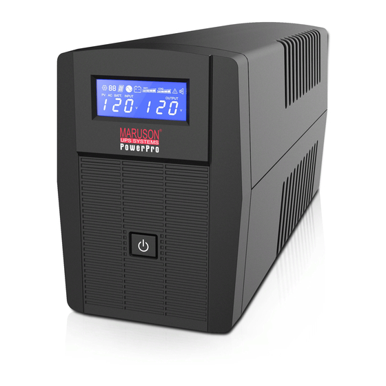
Front Panel—
1. LCD Back-Light
2. Power "ON/OFF" Switch
LONG
202-719-4978
5
Modem/Phoneline Connection
Plug incoming internet line into the "In" socket at the
back of the UPS. Use one more Internet line cable
and plug one end of the Internet line cable to the
"Out" socket at the back of the UPS. Plug the other
end to the modem input socket as shown.
6
Turn On/Off
To turn on the UPS unit, press the power switch lightly.
To turn off the UPS unit, press the power switch again
(When Swith ON,The LED lighting.).
7
LCD Display Specification
The LED will always turns on when UPS works,
including in off charging mode and fault mode.
When LCD start to work, it will display all information
for 3s
1).When in normal mode, it will display as below.
2).When in AVR mode, it will display as below. And the
mark
will flicker every 1second.
UPS System Description
Back Panel—
1. USB Port
1
2. Modem/Phone Line Surge Protection
3. Battery Backup Outlets
2
4. Surge protected outlets
5. AC input
6.
Circuit breakerz
*
3).When in battery mode, it will display as below.
And the mark
Note: If I/P-V<40V,input voltage will display "000"
4).When in off charging mode, it will display as below.
Note: the output voltage always is displayed as "000"
in off charging mode.
5).When in fault mode, it will display as below. "FAULT"
character and the reason of fault only.
Note: the fault code will be showed in fault mode.
6).Load level definition:
Load LEVEL
7).Battery capacity definition:
8).When over load, the mark
1second.
9).When battery low, the mark
1second.
2
3
IEC×3 for 220/230/240V
will flicker every 1second.
Load bar Indication
0%~25%
25%~50%
50%~75%
75%~100%
Battery voltage
≤11V
Battery voltage
11V≤
≤11.5V
Battery voltage
11.5V≤
≤12.5V
Battery voltage
≥12.5V
will flicker every
will flicker every
1
O
U
T
N I
5
6
4
Advertisement
Table of Contents

Related Manuals for Maruson PRO-400A LCD


Summary of Contents for Maruson PRO-400A LCD
- Page 1 Inspection Modem/Phoneline Connection 3).When in battery mode, it will display as below. And the mark will flicker every 1second. Remove the UPS from its packaging and inspect it Plug incoming internet line into the “In” socket at the for damage that may have occurred during shipping. back of the UPS.
- Page 2 During the installation of this equipment it should be assured that the sum of the leakage currents of the UPS and the connected loads does not exceed 3.5mA. The mains socket outlet that supplies the UPS shall be installed near the UPS and shall be easily accessible. MODEL PRO-400A LCD PRO-600A LCD PRO-800A LCD CAPACITY...
Need help?
Do you have a question about the PRO-400A LCD and is the answer not in the manual?
Questions and answers