
Related Manuals for netvox ZigBee Z805A


Summary of Contents for netvox ZigBee Z805A
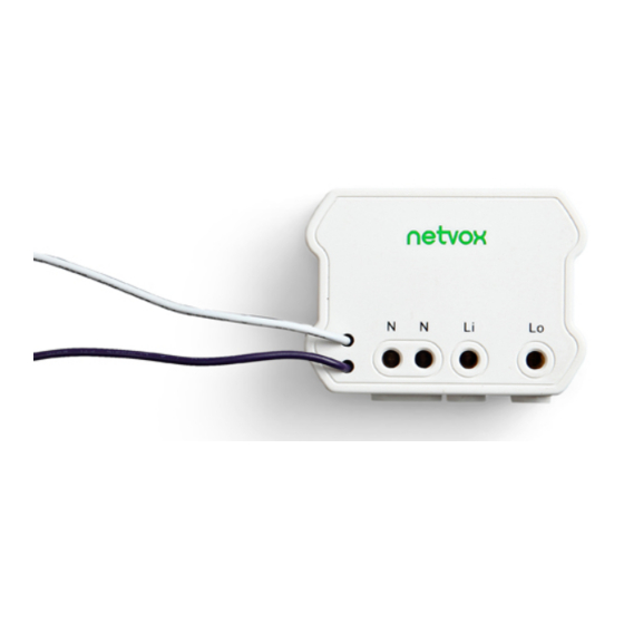
- Page 1 ZigBee Wireless Euro Type Switch Control Unit with Power Meter (1-Output) User Manual Wireless Euro Type Switch Control Unit with Power Meter (1-Output) Model: Z805A Firmware: V3.0/V3.1/V3.2/V3.3 Hardware: V1.0...
-
Page 2: Table Of Contents
4-6. Current / Voltage / Power / Energy Detection....................4 4-7. Reset Power Consumption Summation......................4 4-8. Restore to Factory Setting..........................5 5. Home Automation Clusters for Z805A........................5 6. Loading property..............................7 7. Related Netvox Devices............................7 8. Related Netvox Devices............................8 9. Important Maintenance Instructions........................8... -
Page 3: Introduction
16A/250V AC on-off relay. Users can wireless control the switch through an external switch, bound device or software such as APP. Users could also monitor the power consumptions such as current/ voltage/ power/ energy through Netvox APP. The Z805A is used as a router in the network, allowing other devices to be their sub-devices. -
Page 4: Specification
3. Specification Fully compatible with IEEE 802.15.4 Use the 2.4GHz ISM band for a total of 16 channels 100~240VAC 50/60HZ power supply Communication distance up to 150 meters (depending on specific environmental conditions) Simple operation and setting ... -
Page 5: End Device Bind
4-4. End Device Bind Objects tio be bound: The device with On/Off cluster on the client side, such as the Z501 of NETVOX, or the device with the meter cluster on the client side. (B) Binding operation: B-1. Press and hold the Binding Key for 3 seconds to send the binding request. The Network Indicator will flash green once. -
Page 6: Home Automation Clusters For Z805A
Step1. Press and hold the Binding Key for 15 seconds. The network indicator will flash green 3 times (at the 3 the 10 , and the 15th second). Step2. After releasing the Binding Key, press the Switch Key within 2 seconds. The network indicator will rapidly flash green. - Page 7 1. The Cluster used by the Z825K233 refers to the Cluster ID (0x0702) and Electrical Measurement ClusterID (0x0B04) used by the Simple Metering in the SE. In the Cluster ID (0x0702), Netvox customizes the current, voltage, power, and energy attributes.
-
Page 8: Loading Property
Max. Inductive Max. Load Overload with LEDs Load with Electric Protection (AC) **Remark** Motors with Auto (cosφ=0.4) Remark** Power Cutoff 16A/250V 400W/8 8A/250V 1.5HP/250V LEDs 7. Related Netvox Devices Z810B: Switch control unit with consumption display ZB02C: Switch... -
Page 9: Related Netvox Devices
8. Related Netvox Devices This product does not have a waterproof function. Please place it indoors. Note: 1. When the detected current exceeds the measurement range (16A), the device will automatically disconnect the load within 2 seconds after the detection. At the same time, check whether the Bit1 (Current OverLoad) bit of the attribute ACAlarmsMask is 1, and if it is 1, it will issue a broadcast Alarm, and if it is 0, it will not issue a broadcast alarm.
Need help?
Do you have a question about the ZigBee Z805A and is the answer not in the manual?
Questions and answers