Table of Contents
Advertisement
Advertisement
Table of Contents
Troubleshooting

Related Manuals for ALERTON AZW-5000


Summary of Contents for ALERTON AZW-5000
- Page 1 Installation and Operations Guide AZW-5000 © Honeywell AZW-5000 Rev. 0001BETA...
- Page 2 Trademarks and trade names may be used in this document to refer to either the entities claiming the marks and names or their products. Alerton, BACtalk, and their logos are registered trademarks and VisualLogic is a trademark of Honeywell. Honeywell disclaims any proprietary interest in trademarks and trade names other than its own.
-
Page 3: Table Of Contents
Replacing an AZW-5000 Viewing commissioning data Troubleshooting Troubleshooting weak reception Troubleshooting RSSI flash sequences Troubleshooting devices not found by device scan Troubleshooting erroneous WTS temperature readings Appendix A: AZW-5000 AVs and BVs Appendix B: AZW-5000 Commissioning Record © Honeywell LTBT-TM-AZWIOG Rev. 0001BETA... -
Page 4: About Azw-5000
(up to 15 controllers or devices) wireless subnetwork to a wired network. A scenario where the AZW-5000 would be effective is a school that adds portable class rooms that need to be tied into the existing school Building Automation System (BAS). -
Page 5: Azw-5000 Network Topology
Typical AZW-5000 implementation Items to note in relation to Figure 2: • The maximum number of AZW-5000 devices on a network is 16 (1 coordinator and 15 transceivers/repeaters). • The AZW-5000 connected to the BCM-ETH must be configured as a coordinator. -
Page 6: About This Document And Related Publications
Installation and Operations Guide AZW-5000 About this document and related publications This document provides information about installing and wiring a AZW-5000 to equipment, power, and communication channels. It also shows how to operate the device. Always install equipment in accordance with the National... -
Page 7: General Installation Guidelines
The safest way to size a transformer is to ensure that the maximum VA load rating of the AZW-5000 is less than 85% of the Nameplate VA rating of the transformer. Even if all outputs are not presently used, this ensures that each AZW-5000 has sufficient power for future equipment additions. - Page 8 If the wire diameter is too small, the resistance may be too high, resulting in a low voltage supply to the AZW-5000. This is known as line loss. The wire size is based on the length of the wire run and the current draw of the AZW-5000.
-
Page 9: Ms/Tp Lan Wiring
BCM. Terminating MS/TP LAN cabling MS/TP terminations are located at the top of the AZW-5000. See Fig. 4 on p. 15. Maintain polarity of the MS/TP wire run throughout the MS/TP LAN. Basic information about MS/TP terminations at the AZW-5000 are Note provided here. - Page 10 • Each transceiver MS/TP segment should have a single point of shield ground, preferably as close to the middle of the cabling run as possible. • Do not ground the MS/TP shield to an AZW-5000 GND terminal. • Do not ground both ends of a shield. Differences in potential between the grounds may induce current on the shield, causing interference.
-
Page 11: Configuration
(ON is toward the body of the device). Set the coordinator device ZigBee network address to 0. If the device is associated with an Alerton Wireless Temperature N o t e Sensor, both units must have the same ZigBee MAC address DIP switch settings. -
Page 12: Commissioning
4. Double-click the pushbutton and select Device template (different device) as the button type. The Pushbutton Item dialog box appears. 5. Enter the text for the button label (“AZW-5000 commissioning”, for example). 6. Enter 9999 for the Device instance. 7. Select Use display from and then select the Alerton/Standard rep/job. - Page 13 8. Set the Device Instance. 9. Set the ZigBee Network Number. You can use the default setting as long as it is unique across the BAS. All AZW-5000 devices on a given network must have the same ZigBee Network Number.
-
Page 14: Installation
2. Push down and in to snap the bottom flex connector onto the DIN rail. To remove the AZW-5000 from a DIN rail, push straight up from the bottom to release the top tabs and then pull the top of the device outward. -
Page 15: Wiring
60 pF/foot (200 pF/m). Foil or braided shield is acceptable. Maintain wiring polarity. Connecting power Connect the AZW-5000 to 24VAC power from a UL Listed Class 2 24VAC transformer (not included). The AZW-5000 is a half-wave device. Do not connect half-wave CAUTION devices and full-wave devices to the same AC transformer. -
Page 16: Checking Proper Operation
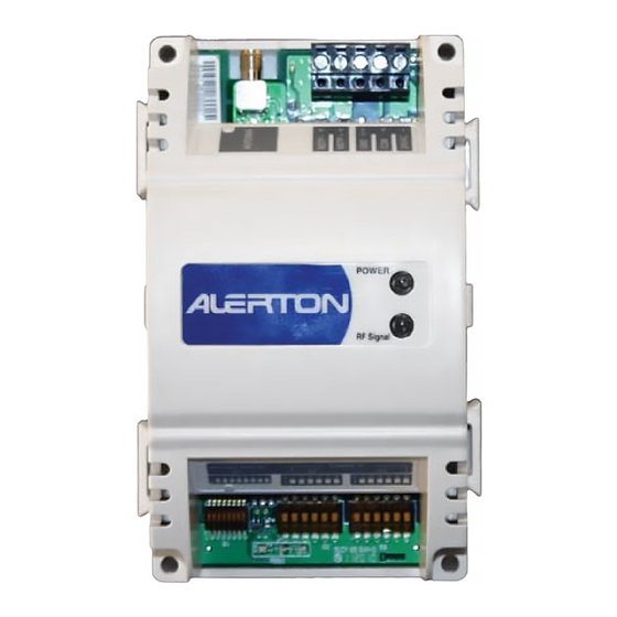
Checking radio communication The RF signal indicator (see Fig. 5 on p. 17) flashes red when the device communicates with another AZW-5000. It flashes yellow to indicate the device is communicating with an Alerton Wireless Temperature Sensor. Checking radio signal strength The radio signal strength indicator (RSSI) LEDs (see Fig. - Page 17 Installation and Operations Guide Installation MS/TP Antenna MS/TP AC power status terminal terminals terminals indicator Power status indicator RF signal indicator Radio signal strength indicator Figure 5 Locations of AZW-5000 components © Honeywell LTBT-TM-AZWIOG Rev. 0001BETA...
-
Page 18: Checking Network Operation
If a device does not appear on the device scan, see “Troubleshooting” on page 22. 4. Check the ASN (http://asn.alerton.com) and verify that the AZW-5000 devices and unitary controllers have the latest ROC file. If they do not, update the ROC files (see “Updating the real-time operating code (ROC) file”... -
Page 19: Adding Alerton Wireless Temperature Sensors
A WTS differs from other devices you might add to an AZW-5000 network because it does not need to be wired to a transceiver. It has an internal radio that acts as its transceiver. You can pair a WTS with an AZW-5000 transceiver or repeater, but not with a coordinator. ... -
Page 20: Maintaining An Azw-5000
Installation and Operations Guide AZW-5000 Maintaining an AZW-5000 This section explains how to update the ROC file, replace an AZW-5000 device, and view commissioning data for a device. Updating the real-time operating code (ROC) file AZW-5000 has downloadable software called real-time operating code (ROC file). -
Page 21: Viewing Commissioning Data
You may need to view commissioning data after initial commissioning. To view settings for a commissioned AZW-5000 1. If the device is not listed in the Device Manager table, perform a device scan and add the device to the table. -
Page 22: Troubleshooting
3. Add an external antenna. See “Attaching an external antenna (optional)” on page 14. 4. Add another AZW-5000 device to act as a repeater. Note that the use of repeaters reduces the overall bandwidth of the network. Troubleshooting RSSI flash sequences The RSSI LEDs show radio signal strength, but will flash if an error occurs. -
Page 23: Troubleshooting Devices Not Found By Device Scan
6. Pull up the problem device in device template 99100017 and check the parameters: Parameter Value Extended PAN ID Same as all other AZW-5000 devices ZigBee Network Same as all other AZW-5000 Number devices, but unique across BAS MS/TP Network... -
Page 24: Appendix A: Azw-5000 Avs And Bvs
Appendix A: AZW-5000 AVs and BVs AZW-5000 points sorted by point number Default Comments Point Function Description Value AV–0 Commissioning ZigBee PAN ID through AV-7 AV–8 Commissioning ZigBee Security Key through AV-23 AV–24 Commissioning ZigBee Group ID AV–25 Commissioning WTS Set Point Adjustment Limit. - Page 25 AZW-5000 points sorted by point number Default Comments Point Function Description Value AV–57 AZW-5000 ZigBee Device Type diagnostics AV–58 AZW-5000 ZigBee BZLL Type diagnostics AV–59 AZW-5000 ZigBee Group ID diagnostics AV–60 AZW-5000 WTS RSSI diagnostics AV–61 AZW-5000 AZW-5000 RSSI diagnostics AV–62...
- Page 26 AZW-5000 points sorted by point number Default Comments Point Function Description Value AV–80 WTS Temperature Reading diagnostics AV–81 WTS Setpoint Adjust diagnostics AV–82 WTS Occupancy Override Status diagnostics AV–83 WTS Battery Status diagnostics AV–84 VAV's AV point for WTS diagnostics Temperature Reading AV–85...
- Page 27 AZW-5000 points sorted by point number Default Comments Point Function Description Value AV–10002 AZW-5000 Free obj mem diagnostics AV–10003 AZW-5000 Router Queued Message count diagnostics AV–10004 AZW-5000 MS/TP RX frames diagnostics AV–10005 AZW-5000 MS/TP TX frames diagnostics AV–10006 AZW-5000 MS/TP RX bytes diagnostics AV–10007...
- Page 28 AZW-5000 points sorted by point number Default Comments Point Function Description Value AV–10029 AZW-5000 MSP Heartbeat Failures diagnostics AV-10100 Network Neighbor table entries Lists the nodes in the device’s communication range, up to 50 nodes. Each through diagnostics, node is assigned an AV with these properties:...
- Page 29 Indicates that commissioning data has been changed in Envision for BACtalk Commissioning and that power needs to be cycled to write the changes to the AZW-5000. Must be manually set to active by the user to initiate a save of the commissioning data when power is cycled.
-
Page 30: Appendix B: Azw-5000 Commissioning Record
Appendix B: AZW-5000 Commissioning Record Use this worksheet to record the configuration and commissioning information for each AZW-5000 device. Date: ____________ Commissioned by: ____________________ ZigBee MS/TP Extended Device MS/TP MAC Address ZigBee MAC Address Device Type Network Network Baud Rate...
Need help?
Do you have a question about the AZW-5000 and is the answer not in the manual?
Questions and answers