Table of Contents
Advertisement
Quick Links
SAVE THESE INSTRUCTIONS
TM Series Water Meters
(Models GG, GX, GA & SC)
Owner's Manual
GENERAL INFORMATION
Flowmeter ................................................................................ 1
GG Model ................................................................................ 3
GX Model ................................................................................. 9
GA Model .............................................................................. 19
SC Model ............................................................................... 20
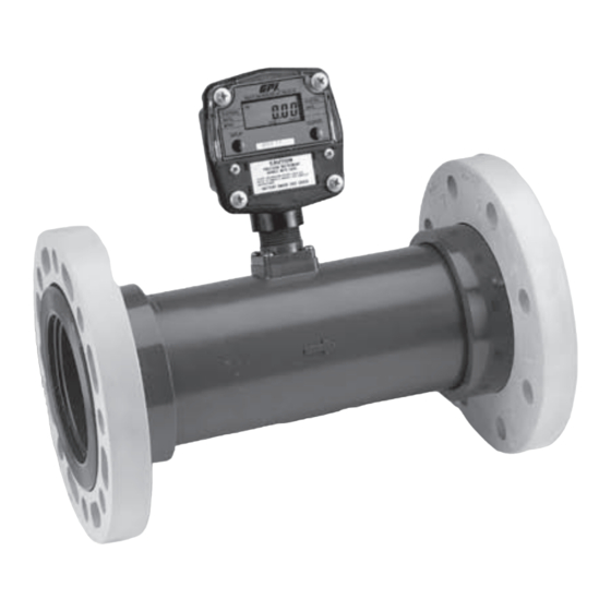
F L O W M E T E R
IMPORTANT NOTICE
Use TM Series meters with water and other chemicals compat-
ible with wetted components (see Specifications Section). Do
not use with fuel or incompatible chemicals. TM Series meters
are available with one of the following electronic options: Local
Display, Conditioned Signal Module (Open-Collector), Local
Display with Pulse-Out (GG Model), Local Display with 4-20 mA
(GX Model), 4-20 mA Output Only (GA Model) or Scaled Output
(SC Model). Refer to each section for details.
These meters are not legal for trade applications.
TM Series meters are very sensitive to electric noise if operated
within 1 to 2 inches of some electric motors or other sources
of electronic noise.
04/10
GX Model
Connections
Install your meter in-line either horizontally or vertically or at
the end of the hose adjacent to the nozzle. Installation to metal
connections is not recommended. Install as follows:
1. Plan to install turbine with a minimum straight pipe length
as follows:
• Upstream from the turbine, allow a minimum straight pipe
length of 10 times the internal diameter of the turbine.
• Downstream from the turbine, allow a minimum straight
pipe length of 5 times the internal diameter of the turbine.
2. For Spigot (Pipe) End - Use only primer and solvents ap-
proved for PVC gluing.
Cut to Length - The meter housing can be shortened by the
customer. Each meter has a "dotted" line feature molded
on the top surface of the housing tube. The housing can be
cut up to this line without harming any internals.
Most glue on fittings will fit without interfering with the com-
puter display area. However, the customer should check all
parts before attempting cut.
For NPT Fittings - Wrap all connections with 3 to 4 wraps
of thread tape. Make sure the tape does not intrude into the
flow path.
3. Attach meter with arrow pointed in the direction of the flow.
4. For NPT Fittings - Hand tighten the meter at the housing
ends. Do not use a wrench or similar tool to tighten. This
can damage the housing.
GG Model
INSTALLATION
Rev. - 920863-01
1
Advertisement
Table of Contents

Related Manuals for Accu-Flo Meter Service TM Series

Summary of Contents for Accu-Flo Meter Service TM Series
- Page 1 These meters are not legal for trade applications. 3. Attach meter with arrow pointed in the direction of the flow. TM Series meters are very sensitive to electric noise if operated 4. For NPT Fittings - Hand tighten the meter at the housing within 1 to 2 inches of some electric motors or other sources ends.
-
Page 2: Specifications
U.S. Measurement 5. For Flange Fittings - Customer to provide: • Ring Gaskets or Full-Face Gaskets approved for use with ANSI flanges and the fluid being monitored (two required). Unit of Measure: Gallon • 5/8" bolts and nuts: Four per side for 3-inch meters; eight Flow Range: per side for 4-inch meters. -
Page 3: Important Notice
PARTS G G M O D E L The following replacement parts and accessories are available IMPORTANT NOTICE for the TM Series meters: Part No. Description This manual will assist you in operating and maintaining the GPI electronics supplied with your GPI meter. The GPI Electronics... -
Page 4: Operation
Make sure you meet the meter’s minimum flowrate requirements: 1, TOTAL 2 BATCH and FLOWRATE. Press DISPLAY briefly to display the TOTAL 2 BATCH. Hold the DISPLAY button for 3 TM Series Meters seconds to reset the Batch Total to zero. 3 inch meter 30 GPM (113.6 LPM) -
Page 5: Connecting The Equipment
4. All enabled units-of-measure remain visible and selectable T E R M I N A L L O C A T I O N S – the entered correction will be applied to all enabled units. 5. To return to factory calibration (FAC), press and hold both CALIBRATE and DISPLAY buttons for about 3 seconds until FAcCAL is displayed. - Page 6 P O W E R S I G N A L O U T P U T Open Collector 9V Battery (included) 9V_BAT+ Connect battery (included) red wire (+) to terminal. OC_OUT Connect signal wire to terminal. Connect battery (included) black wire (–) to any terminal.
-
Page 7: Troubleshooting
MAINTENANCE Replacing the Battery Replace the battery when the readout becomes dim or blank. Replace the battery with a 9-volt lithium battery. Order GPI part number 902006-44. To replace the battery: 1. Remove the two large screws and two small screws from the battery coverplate. - Page 8 ILLUSTRATED PARTS DRAWING – GG MODEL Item Item No. Part No. Description Req’d. No. Part No. Description Req’d. 120009-2 Battery Cover ............1 906005-47 Threaded Plug ............1 120028-1 Battery Gasket ............1 906005-48 Seal ................. 1 902006-44 Battery, 9-volt Lithium ..........1 904005-63 Screw, 4-40 x 3/16 in.
- Page 9 SPECIFICATIONS – GG MODEL G X M O D E L Materials: IMPORTANT NOTICE Acetal, Amorphous Nylon, PET Polyester, Polyester (de- cals), Viton (gasket & seals), Stainless Steel (fasteners) Power Source: This manual will assist you in operating and maintaining the GPI Battery (9V): 6.5V to 20V acceptable range.
-
Page 10: Cable Guidelines
Environmental Terminal Connections Avoid plumbing meter where the 4-20 mA Out with Display is: Remote Transmitter INPUTS / OUTPUTS • Subject to constant exposure to water or other liquids (oc- ISO-IN COM: N/A casional low-pressure splashing will not harm unit if cable ISO-IN COM ISO-LF IN: N/A entry points are well-sealed). - Page 11 W I R I N G D I A G R A M 1 — 4-20 mA or 0-20 mA Output — Customer Equipment With Built-in Power Supply Output: Customer Equipment, 0-20 mA Sensing, Built-in Loop Power Supply INPUTS OUTPUTS Loop (+) 4-20 mA Out with Display...
- Page 12 W I R I N G D I A G R A M 3 — 0-5 V Output — Customer Equipment Without Built-in Power Supply Output: Customer Equipment, 0-5 V Sensing, Separate Loop Power Supply Loop Power Supply INPUTS OUTPUTS Typ 12 –...
- Page 13 Make sure you meet the meter’s minimum flowrate requirements: 1, TOTAL 2 BATCH and FLOWRATE. Press DISPLAY briefly to display the TOTAL 2 BATCH. Hold the DISPLAY button for 3 TM Series Meters seconds to reset the Batch Total to zero. 3 inch meter 30 GPM (113.6 LPM)
- Page 14 4. All enabled units-of-measure remain visible and selectable 3. While watching the transmitter’s indicating light, press and – the entered correction will be applied to all enabled units. hold both its “SET” and “20” buttons. Release them when the light blinks. 5.
-
Page 15: Maintenance
(faster) response time to achieve the best transmitter perfor- mance. • Shorter (faster) response times are preferable for sensors that generate higher frequency outputs (GPI TM Series Meters, for example). • Longer (slower) response times are also appropriate in situ- ations where sensor-output frequency fluctuates or wobbles substantially. - Page 16 TROUBLESHOOTING SYMPTOM PROBABLE CAUSE CORRECTIVE ACTION A. METER IS NOT 1. Field Calibration not performed properly. Field Calibrate again or select Factory Calibration. ACCURATE 2. Factory Calibration not suitable for Perform a Field Calibration according to Calibration Section or liquid being measured. select the proper Factory Calibration selection (i.e., gallon or litre).
- Page 17 ILLUSTRATED PARTS DRAWING – GX MODEL Item Item Part No. Description Req’d. Part No. Description Req’d. 120512-01 Switch Keypad Kit ............1 906005-47 Threaded Plug ..............120048-01 Gasket ................1 902005-9 Strain Relief ..............12052102 Computer Kit ..............1 901002-87 O-Ring ................120043-01 PCB Assembly ..............1 120054-01 Main Circuit Assembly ............1...
- Page 18 SPECIFICATIONS – GX MODEL Cable: 20 ft., 3 conductor, shielded (Belden 9363). Applications: Mechanical Connections: Use for indoor or outdoor applications where occasional Display is mounted directly to flow meter body via 1-inch NPT. moisture is common. Electrical Connections: Materials: One strain relief port: one threaded plug (1/2 x 20).
- Page 19 ILLUSTRATED PARTS DRAWING – G A M O D E L GA MODEL All information needed for the GA Model can be found in the GX Model sections. Consult one or all of the following: Important Notice ..............9 Safety Instructions ..............9 Installation ................9 Wiring ..................10 Wiring Diagrams ..............11...
- Page 20 • Close to high voltage/current runs, DC motors, internal S C M O D E L combustion engines or frequency inverters. • Excessive vibration. IMPORTANT NOTICE Cable Guidelines GPI flowmeters have a “K-factor” which is the pulse output per The open collector signal itself is very resistant to electrical unit volume measured stated as “Pulses Per Gallon”...
- Page 21 T E R M I N A L C O N N E C T I O N S COIL-A: To flowmeter sensor. COIL-B: To flowmeter sensor. HL-HF IN: N/A HL-LF IN: N/A +5-30 VDC COM: Local Common (3 terminals are equivalent) COIL-A COIL-B O.C.
-
Page 22: Power Supply
Power Supply The “X” markers represent the digits of the K-factor. This allows a K-factor range of 0000.1 to 9999.9. The switches are arranged The GPI Scaled Pulse circuit is designed to operate correctly and labeled as follows: when supplied with any DC voltage between about 5-30 volts, referenced to any of the COM terminals. - Page 23 If you need to set a very large K-factor (larger than 9999.9), with a standard unit, you will have to follow the instructions for getting an output pulse every 1/10th unit. That is, multiply the meter’s K-factor by 0.1, and then enter the result on the switches. Remember that you will get an output pulse every 1/10th unit instead of every whole unit.
- Page 24 TROUBLESHOOTING SYMPTOM PROBABLE CAUSE CORRECTIVE ACTION A. NO OUTPUT ACTIVITY 1. Signal too weak. Supply stronger signal. WHEN USING “COIL” OR “HL-HF-INPUT” 2. Frequency above 1500 Hz. Supply lower frequency. 3. Electronic failure. Contact factory. B. NO OUTPUT ACTIVITY 1. Signal too weak. Supply stronger signal.
- Page 25 ILLUSTRATED PARTS DRAWING – SC MODEL Item Part No. Description Req’d. 120059-01 Blank Coverplate Kit ............1 12052101 Circuit Assembly Kit ............1 120517-01 Adapter Kit ................1 125066-20 Cable, 20 ft...............1 901002-82 O-Ring ................1 901002-87 Seal ...................2 902005-9 Strain Relief ..............2 904002-44 Sealing Screw, 1/4 - 20 x 5/8"...
-
Page 26: Weee Directive
SPECIFICATIONS – SC MODEL SERVICE For warranty consideration, contact your local distributor. If Applications: you need further assistance, contact the GPI Customer Service Use for indoor or outdoor applications where occasional Department at: moisture is common. Toll free: 1-888-996-3837 Materials: Acetal, Polyester (decals), Viton (gasket &... -
Page 28: Limited Warranty Policy
Limited Warranty Policy Great Plains Industries, Inc. 5252 E. 36 Street North, Wichita, KS USA 67220-3205, hereby provides a limited warranty against defects in mate- rial and workmanship on all products manufactured by Great Plains Industries, Inc. This product includes a 1 year warranty. Manufacturer’s sole obligation under the foregoing warranties will be limited to either, at Manufacturer’s option, replacing or repairing defective Goods (subject to limitations hereinafter provided) or refunding the purchase price for such Goods theretofore paid by the Buyer, and Buyer’s exclusive remedy for breach of any such warranties will be enforcement of such obligations of Manufacturer.
Need help?
Do you have a question about the TM Series and is the answer not in the manual?
Questions and answers