Table of Contents
Advertisement
Quick Links
Advertisement
Table of Contents

Related Manuals for Sygonix 2380478


Summary of Contents for Sygonix 2380478
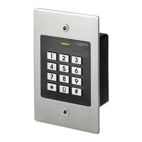
- Page 1 Operating Instructions RFID code lock Item no. 2380478...
-
Page 2: Table Of Contents
Table of contents Page Introduction ................................4 Explanation of symbols ............................4 Intended use ................................5 Delivery content ..............................5 Safety information ..............................6 Controls and connections ............................7 Installation and connection ..........................8 a) Installation ..............................8 b) Connecting to conventional voltage/power supply ..................9 c) Connecting to alarm system ..........................9 d) Wiegand interface ............................10 Operation ................................ - Page 3 Page 10. Operation ................................29 a) Getting started .............................29 b) Accessing via valid user transponder ......................30 c) Accessing via valid user code ........................30 d) Access via valid user transponder and user PIN ..................30 e) Accessing via door opener button .......................30 11. Troubleshooting ..............................31 12.
-
Page 4: Introduction
1. Introduction Dear customer, Thank you for purchasing this product. This product complies with statutory, national and European regulations. To ensure that the product remains in this state and to guarantee safe operation, always follow the instructions in this manual. These operating instructions are part of this product. -
Page 5: Intended Use
3. Intended use This product is designed to prevent unauthorised access to doors (e.g. in an office) and to activate/disable alarm systems. The product enables to save up to 1000 users with different transponders and user codes. A valid access attempt activates a potential-free relay changeover contact (see contact rating under “Technical data”). In this case, for example, a door opener or an alarm system can be triggered. -
Page 6: Safety Information
5. Safety information Damage caused due to failure to observe these instructions will void the warranty. We shall not be liable for any consequential damage! We shall not be liable for damage to property or personal injury caused by incorrect handling or failure to observe the safety information! Such cases will void the warranty/guarantee. -
Page 7: Controls And Connections
6. Controls and connections 1 Opening for wall mounting 2 LED indicator 3 Keypad with an integrated RFID sensor behind it There is a brightness sensor on the rear, which serves as tamper protection. Connecting cable: Colour Inscription Function 12 - 18 V/DC Power supply 12 - 18 V/DC Black GND/ground... -
Page 8: Installation And Connection
7. Installation and connection Ensure that the connection cables are not kinked or squashed. This can cause malfunctions, short circuits and device defects. Ensure that no cables or wires are damaged when drilling holes or tightening screws. Installation and connection may only be carried out when power supply is switched off. Make sure that the brightness sensor on the back is not exposed to light beams after installation, as switch- ing on the system could cause activation of tamper protection with subsequent locking of all functions. -
Page 9: B) Connecting To Conventional Voltage/Power Supply
b) Connecting to conventional voltage/power supply When a conventional power supply unit should be used, observe the following figures with the wiring diagram. A) “Fail-secure” door opener: Releases the locking latch only when its operating voltage is applied (common design for front doors). -
Page 10: D) Wiegand Interface
d) Wiegand interface There are two application options for the Wiegand interface of the code lock: 1) The code lock is used as an external card reader The code lock can be connected to a compatible Wiegand controller and used as an external card reader. The Wiegand controller must support a 26-bit protocol that is used for the transmission of transponder data. -
Page 11: Operation
8. Operation After completing the installation and connection process, switch on the operating voltage. The code lock will emit a short beep and the red LED will light up. This indicates that the code lock is in standby mode. You can now start programming, see next section. -
Page 12: Programming
9. Programming Important! We recommend that you note all settings. You will thus be able to refer to them over time and adapt them to new requirements. You should note access data such as user name, memory cell number, transponder number, user code etc., to know who can access the system. -
Page 13: A) Enabling/Disabling Programming Mode
a) Enabling/disabling programming mode • To enable the programming mode, enter the master code (factory setting = 123456): Each time you press a button, the code lock emits a short confirmation beep. • The LED then flashes red (programming mode is active). This mode allows pairing and deleting user transponders or making various settings. -
Page 14: C) Pairing User Transponders
c) Pairing user transponders The code lock has a total of 990 memory cells in which user transponders can be paired or, alternatively, user codes can be stored. You can use both the keypad and the master transponder for pairing. We recommend that you create a table and fill in all access data, such as user name, memory cell number, user code, transponder number, etc. - Page 15 User transponder is assigned to a specific memory cell: Although this pairing process takes more time, it enables to delete a specific user transponder (via the memory cell number) even when it is defective or lost. This procedure is also advisable if you are planning to use the code lock with user transponders and user codes.
-
Page 16: D) Deleting The User Transponder
d) Deleting the user transponder The respective user will no longer have access once the corresponding user transponder has been deleted. Deletion is possible either via the user transponder or the memory cell number. User transponders can also be deleted with the master transponder. When the user transponder is deleted, the corresponding user PIN, if any, will be deleted as well. -
Page 17: E) Saving A User Code
e) Saving a user code The code lock has a total of 990 memory cells in which user codes can be stored or, alternatively, user transponders can be paired. We recommend that you create a table and fill in all access data, such as user name, memory cell number, user code, etc. - Page 18 User code is assigned to a specific memory cell: Although this saving procedure takes more time, it enables to delete a specific user code (via the memory cell number) even when it is lost. This procedure is also advisable if you are planning to use the code lock with user transponders and user codes.
-
Page 19: F) Deleting The User Code
f) Deleting the user code The respective user will no longer have access once the corresponding user code has been deleted. User codes can be deleted via the user code or the memory cell number. Proceed as follows: • Enable the programming mode as described in section 8. a); the LED starts to flash red. •... -
Page 20: H) Selecting The Access Mode
h) Selecting the access mode The changeover contact can be activated in three different ways. The access mode can be changed for this purpose. • Access with user transponder or user code (default setting) Holding a valid user transponder in front of the RFID sensor activates the changeover contact. Alternatively, enter the stored user code and press the button to confirm. -
Page 21: I) Saving A User Pin
i) Saving a user PIN When the access mode has been set to as described in section 8. h), each transponder must be assigned an additional user PIN. This access mode provides activation of the changeover contact only after recognition of a valid transponder and entering a valid user PIN and confirming with the button. -
Page 22: J) Changing A User Pin
j) Changing a user PIN A user PIN can be changed in two different ways: • User PIN can be changed by means of the user transponder (this is a perfect option for users since they do not normally know the memory cell number) •... -
Page 23: K) Setting The Changeover Contact Activation Time
k) Setting the changeover contact activation time This function enables to set the changeover contact activation time from 1 to 99 seconds after a valid access to the code lock (default setting is 5 seconds). When “0” is set, the changeover contact goes to “toggle” mode. Each valid access to the code lock changes the changeover contact switch position. -
Page 24: L) Enabling Or Disabling Protection Against Incorrect Entries
l) Enabling or disabling protection against incorrect entries This function enables to set whether the code lock should be blocked in case of 10 or more incorrect entries in a row (by default: disabled). Proceed as follows: • Enable the programming mode as described in section 8. a); the LED starts to flash red. •... -
Page 25: N) Visitor Transponder Or Visitor Code
n) visitor transponder or visitor code The code lock can store up to 10 different visitor transponders or visitor codes. Memory cell numbers 990 - 999 are provided for them. Visitor transponders or visitor codes can have a pre-programmed number of access attempts (1 to 10 attempts), after which they will become invalid. - Page 26 2) Saving the visitor code • Enable the programming mode as described in section 8. a); the LED starts to flash red. • Enter the programming code . The yellow LED will then light up. • Enter the number of times the visitor code may be used ( ..
-
Page 27: O) Resetting All Settings To Factory Defaults; Pairing A New Master Transponder
3) Deleting the visitor transponder or visitor code After the preprogrammed number of access attempts has been used, the code lock automatically deletes the visitor transponder or visitor code from the memory. The cleared memory cell number is now available for programming another visitor transponder or visitor code. - Page 28 1) Resetting the code lock and paring master transponders • De-energise the code lock and wait for the LED to go off. • Keep the button pressed. • Reconnect the code lock to the voltage/power supply. The code lock will emit two beeps. Now release the button.
-
Page 29: Operation
10. Operation a) Getting started Power on the code lock once it has been connected and installed. After powering on, the code lock will emit a beep and the red LED will glow steadily (standby). The code lock is now ready for use and can be programmed. If the code lock continuously emits beeps with the LED flashing quickly, it means that the brightness sensor on the back has activated tamper protection and disabled all functions. -
Page 30: B) Accessing Via Valid User Transponder
b) Accessing via valid user transponder Access with a user transponder only is possible if setting has been selected for access mode (see section 8. h). Make sure you hold the user transponder in front of the code lock (no farther than 3 cm). Once the code lock has recognised the transponder, the changeover contact and door opener are activated for a preset time and the green LED lights up. -
Page 31: Troubleshooting
11. Troubleshooting Preprogrammed settings are not affected by a power cut. However, the code lock will be non-operational during a power cut. For safety reasons, we recommend that you use an uninterruptible power supply for the code lock (as in case of an alarm system) depending on the intended use. - Page 32 New user transponder cannot be paired • Make sure you hold one transponder in front of the RFID sensor at a time (see section 6, clause 3). • The distance between the transponder and the code lock should not exceed 3 cm. •...
-
Page 33: Cleaning And Maintenance
12. Cleaning and maintenance This product does not require maintenance. Use a dry, lint-free cloth for occasional cleaning. In case of heavy soiling, lightly moisten the cloth with water. Never use aggressive detergents, rubbing alcohol or other chemical solutions, as they can cause discolouration or erase button inscriptions. -
Page 34: Technical Data
15. Technical data Power supply ........12 - 18 V/DC Current consumption ......standby < 30 mA Frequency range ........124.6 - 125.4 kHz Transmission power......11.62 dBm Max. reading distance ......approx. 3 cm Data retention in case of a power cut ...yes Suitable transponders ......Commercially available EM transponders for frequency 125 kHz Output ...........Potential-free single-pole changeover contact (relay) Max. - Page 36 This is a publication by Conrad Electronic SE, Klaus-Conrad-Str. 1, D-92240 Hirschau (www.conrad.com). All rights including translation reserved. Reproduction by any method, e.g. photocopy, microfilming, or the capture in electronic data processing systems require the prior written approval by the editor. Reprinting, also in part, is prohibited. This publication represent the technical status at the time of printing.
Need help?
Do you have a question about the 2380478 and is the answer not in the manual?
Questions and answers