
Related Manuals for ITS Telecom EKSELANS CM 8SH-TC


Summary of Contents for ITS Telecom EKSELANS CM 8SH-TC
- Page 1 USER MANUAL CM 8SH-TC 082255 DVB S/S2 TO COFDM/QAM TRANSMODULATOR ITS Partner O.B.S S.L · Av. Cerdanyola 79-81 Local C 08172 Sant Cugat del Vallés · Barcelona (Spain) Phone: +34935839543 · info@ek.plus · www.ek.plus...
-
Page 2: Table Of Contents
CM 8SH-TC USER MANUAL TABLE OF CONTENTS INTRODUCTION: ............................................. 3 Description: ............................................3 Key features: ............................................3 Package contents: ........................................... 3 CONNECTIONS AND INTERFACES: ..................................4 INSTALLATION AND WIRING: ....................................5 General installation and wiring: ..................................... 5 Installation of a multi-module head-end: ..............................6 “CM Management”... -
Page 3: Introduction
CM 8SH-TC USER MANUAL INTRODUCTION: Description: It is a 4 input – 8 tuner DVB S/S2 + USB 2.0 + HDMI IN, with dual CI transmodulator, transmodulated to 4 FLEXIBLE COFDM/QAM, 13/18V, 22KHz and DiSEqC output channels. 95 dBuV output level. MER (Modulation Error Rate) >32dB. -
Page 4: Connections And Interfaces
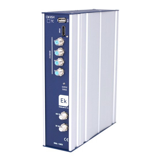
CM 8SH-TC USER MANUAL CONNECTIONS AND INTERFACES: 1. USB input 2. HDMI input 3. Status LED. Status information of the input tuners. 4. Input connectors to each tuner. 5. Status LED. Reports the status of the COFDM/QAM modulated output. The output will be working properly when the LED blinks green. -
Page 5: Installation And Wiring
CM 8SH-TC USER MANUAL INSTALLATION AND WIRING: General installation and wiring: 1.- For installations of several modules (head-end) or a single module, mount the transmodulator module to a wall chassis (CHM TR) or to a rackmount chassis (CHR TR). To do this, mount the supplied metal piece (COD: 251008) on the upper rear part of the module as shown in the image. -
Page 6: Installation Of A Multi-Module Head-End
CM 8SH-TC USER MANUAL 5c.- PC - CM PR programming via USB. Connect the module to the device using the power and data cable. Connect the PC to the CM PR via USB cable. 6.- Run the PC SW programming. Important note: Connect the FA 524 power supply or the... - Page 7 CM 8SH-TC USER MANUAL For the LAN, select the equipment and for connection press: • ID.: enter the MAC of the corresponding power supply. • KEY: enter the CM Key, if any. If not “0”. • LOCAL IP: the local IP will be entered if connected via LAN from the same network. •...
-
Page 8: Cm 8Sh Ci-Tc Module Configuration
CM 8SH-TC USER MANUAL The main “CM Management” screen enables easy identification of the different modules connected to the power supply, as can be seen in the following screen: Power supply and head-end manager (red). Identification of a module with an input card (green) and an output card (blue). Identification of a module with only one input card (green), two CIs (orange) and one output card (blue). -
Page 9: Input Card
CM 8SH-TC USER MANUAL Input card: In this part of the menu the input card will be configured. Selecting A, B, C, D, E, F, G or H in order to choose the input tuner that is to be configured: On: Click on “Check”... -
Page 10: Program Pool
CM 8SH-TC USER MANUAL Program pool: In this table all channels, services, which correspond to the selected entries will be listed. From here the services that are wished to be assigned to each MUX output can be selected. Each service is assigned to the input tuner from which it has been tuned. -
Page 11: Dvb-C Output Card
CM 8SH-TC USER MANUAL Information window on each MUX output throughput: Four bars are displayed corresponding to each MUX output. The green line indicates the percentage of channel occupied. The number above indicates the total throughput being transmitted. At the end of each bar there are two numbers: the first number indicates the throughput being modulated on that channel and the second the maximum possible throughput for the selected modulation parameters. -
Page 12: Remote Head-End Management
CM 8SH-TC USER MANUAL Flow: Adjustment of the data transfer rate to the output: As a general rule, we will set the FTA (Free to Air) modules to 160Mbps. Example flow calculation: 31668Mbps x 4 = 126672 Mbps - The value above would be 160 Mbps. Remote head-end management: The CM head-end can be managed remotely. -
Page 13: Faqs
CM 8SH-TC USER MANUAL Address and port of the data server which facilitates the remote connection. It is configured by default. DO NOT CHANGE. FAQS • What loads can be used for the module? Use isolated loads CF 2150 A (163002) type •... -
Page 14: Configuration Example
CM 8SH-TC USER MANUAL • How can I see the configuration examples? Example 1: Configuration Exa mple Input 1: ON – Tuner A – 22KHz. Enabled. ASTRA 19.2ºE Satellite – Frequency 12545 HORIZONTAL 22000 12545-10600=1945Mhz. No DISEQ. Input 1 – Standard: DVB S channels in the COFDM modulated program pool 1 –... - Page 15 CM 8SH-TC USER MANUAL Example 2: Input 2: ON – Tuner B – 22KHz. Disabled. ASTRA 19.2ºE Satellite – Frequency 10891 HORIZONTAL 22000 10891-9750=1141Mhz. No DISEQ. Input 1 – Standard: DVB S2 6 channels in the COFDM modulated program pool: 2 –...
Need help?
Do you have a question about the EKSELANS CM 8SH-TC and is the answer not in the manual?
Questions and answers