
Related Manuals for AQUALEAK EMS-5


Summary of Contents for AQUALEAK EMS-5
- Page 1 Read these instructions carefully before using this product. Keep these instructions in a safe place for future reference. EMS-5 / 10 Water Leak Detection System Instruction Manual...
- Page 2 Publisher: Aqualeak Ltd. Publication date: 20 December 2021. Version number: 1.0. All possible care has been taken in the preparation of this manual, but Aqualeak, its agents and distributors accept no liability for any inaccuracies that may be found. This manual reflects the state of the product at the publication date below, but further enhancements while in service may mean that the manual does not precisely reflect your system.
-
Page 3: Table Of Contents
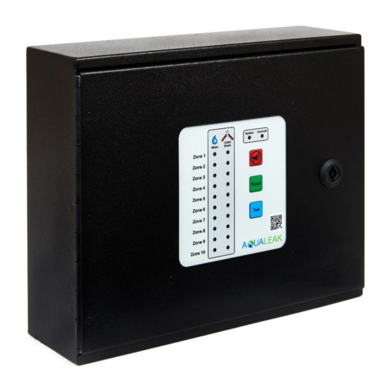
Environmental Monitoring System (EMS-5 / 10) Instruction Manual Contents Safety Information ..................... 5 Intended Use ...................... 5 Statutory Obligations..................... 5 Electrical Safety ....................5 Installation Safety ....................6 Post-Installation Safety ..................6 Product Overview ...................... 7 Technical Specifications ..................8 Input-Output Connections .................. - Page 4 Environmental Monitoring System (EMS-5 / 10) Instruction Manual Figures Figure 1: Aqualeak EMS-10 ....................7 Figure 2: EMS-5 / 10 Input-Output Connections ..............9 Figure 3: EMS-10 Three-Zone Communications Room Example ........... 11 Figure 4: Master Panel Electrical Power Connections .............. 12 Figure 5: Sensor Cable Connection to Interface Board .............
-
Page 5: Safety Information
Environmental Monitoring System (EMS-5 / 10) Instruction Manual 1 Safety Information To ensure your safety and the safety of others, please ensure that you read the Safety Information below before you install or operate this product. 1.1 Intended Use Only use this product for the intended purpose described in this manual. -
Page 6: Installation Safety
Environmental Monitoring System (EMS-5 / 10) Instruction Manual 1.4 Installation Safety RISK OF DAMAGE RISK OF INJURY ✓ ✓ Install the product on a hard, solid, and Be aware of any existing electrical (e.g. level surface. wiring), water (e.g. pipes), or other installations in the vicinity (including ✓... -
Page 7: Product Overview
Operation In operation, the EMS-5/10 continuously monitors all independent sensing circuits connected to it to reduce risks from flooding. If a leak or cable break is detected, the EMS-5/10 will and/or can be configured to: Activate a visual alarm Activate default outputs... -
Page 8: Technical Specifications
Environmental Monitoring System (EMS-5 / 10) Instruction Manual 2.1 Technical Specifications Notes Master Panel Specification Dimensions 335 x 270 x 110 mm Millimetres. Width x Height x Depth Weight 4.5 KG Kilograms Supply Voltage 80 – 264 VAC Volts / Alternating Current. 50/60 Hz... -
Page 9: Input-Output Connections
Environmental Monitoring System (EMS-5 / 10) Instruction Manual 2.2 Input-Output Connections Figure 2: EMS-5 / 10 Input-Output Connections... -
Page 10: Table 2: Ems-5 / 10 Input-Output Connections
Environmental Monitoring System (EMS-5 / 10) Instruction Manual Item Name Notes Relay Abbreviations Configurable Relays 5 or 10 Configurable Relays Relay terminals Interface Board 5 or 10 Zone Inputs are marked Watchdog Relay Relay 15 NC | COM | NO... -
Page 11: Multiple Zone Application Example
Environmental Monitoring System (EMS-5 / 10) Instruction Manual 2.3 Multiple Zone Application Example Aqualeak EMS water leak detection and prevention systems are based on a modular design. Parts supplied depend upon intended application and particular requirements. Once the individual components have been selected, the system can be built and installed. -
Page 12: Installation
Environmental Monitoring System (EMS-5 / 10) Instruction Manual 3 Installation Risk of electric shock and equipment damage! Ensure you have read section 1 Safety Information before attempting installation. 3.1 Master Panel Installation 3.1.1 Mounting The Master Panel has knock-outs for electrical cables on the top, bottom and lower rear of its enclosure. -
Page 13: Relays And Sensors
Environmental Monitoring System (EMS-5 / 10) Instruction Manual 3.2 Relays and Sensors Although multiple sensors and sensor types may be connected to the unit, there must always be an end of line (EOL) terminating resistor at the end of the sensing circuit to allow for cable break monitoring and alarm reference set point. -
Page 14: Sensor Connections
Environmental Monitoring System (EMS-5 / 10) Instruction Manual 3.2.2 Sensor Connections Interface Board (5 or 10 zone) For unpopulated zones, leave resistor terminated in zone plug. Remove resistor on populated zones. Motherboard Green and white cores not used Belden 9534 EIA RS-232 Multicore Cable (4 Core, 24 AWG, 0.2 mm²) -
Page 15: Figure 7: Sensor Cable Using Lc10/Lcb100 And Start Of Line
Environmental Monitoring System (EMS-5 / 10) Instruction Manual Sensor Cable (SCY) using LC10/LCB100 and Start of Line Green and white cores not used SENSE TERMINAL LOOP TERMINAL Red Core: +/1 block not used Black Core: -/2 Belden 9534 Cable to... -
Page 16: Figure 8: Sensor Cable Using Single Esd Sensor Probe
Environmental Monitoring System (EMS-5 / 10) Instruction Manual Single Environmental Sensing Device (ESD) Sensor Probe RED EOL SWITCH ‘IN’ position Green and white cores not used LOOP TERMINAL SENSE TERMINAL block not used Red Core: +/1 Black Core: -/2 Secure cable under clamp... -
Page 17: Figure 9: Multiple Esd Sensor Probes To A Single Zone
Environmental Monitoring System (EMS-5 / 10) Instruction Manual Multiple Environmental Sensing Device (ESD) Sensor probes to a Single Zone ESD #3: RED EOL SWITCH ESD #2: RED EOL SWITCH ESD #1: RED EOL SWITCH ‘IN’ position ‘OUT’ position ‘OUT’ position... -
Page 18: Ancillary Devices
Environmental Monitoring System (EMS-5 / 10) Instruction Manual 3.3 Ancillary Devices 3.3.1 Signalling to Ancillary Device The EMS can be connected to provide a signal to a range of ancillary devices such as a Building Management System (BMS) or Short Message Service (SMS) alarm unit. -
Page 19: 230V Output To Ancillary Device
Environmental Monitoring System (EMS-5 / 10) Instruction Manual 3.3.3 230V Output to Ancillary Device The EMS can be used to control a powered ancillary device such as beacons or solenoid valves. Maximum demand of all connected ancillary devices will be governed by the supply fuse in the unswitched spur, and cable of a suitable cross-sectional area should be used. -
Page 20: Operation
See also section 5 Maintenance for System LED and sounder combinations that indicate there may be a problem with the EMS itself. All operations of the EMS-5 and 10 are undertaken via the front panel: Figure 14: EMS-10 Front Panel... -
Page 21: Monitor Mode
Environmental Monitoring System (EMS-5 / 10) Instruction Manual 4.1 Monitor Mode Standard mode of operation. System LED SOLID GREEN Touch Button(s) Hold Time Effect Mute Instant Disable sounder. Reset Instant Disable sounder (if mute not already pressed). Test Instant Test EMS. Sounder will engage, all relays will latch, and communications to the interface will cease for 10 seconds. -
Page 22: Alarm Mode
Environmental Monitoring System (EMS-5 / 10) Instruction Manual 4.3 Alarm Mode Occurs automatically if the presence of water (i.e. a leak) or excess humidity is detected. Relevant water zone LED(s) FLASH RED Touch Button(s) Hold Time Effect Mute Instant Disable sounder. -
Page 23: Maintenance
5.2 Troubleshooting The table below lists the most common problems and their solutions. If a problem cannot be solved then please call support on +44 (0)1249 715698 or visit our website at www.aqualeak.com. Possible Solution Problem Possible Cause... -
Page 24: Warranty
The Aqualeak Environmental Monitoring System (EMS-05) Water Leak Detector has a 1-year back-to-base warranty as standard, and a 5-year warranty where installed and annually maintained by Aqualeak. The warranty is applicable from the original purchase date and includes repair or replacement if the product is defective. - Page 25 Do not dispose with household waste! According the European Guideline 2002/96/EC for Waste Electrical and Electronic Equipment and its implementation into national right, measuring tools that are no longer usable must be collected separately and disposed of in an environmentally correct manner.
Need help?
Do you have a question about the EMS-5 and is the answer not in the manual?
Questions and answers