ASCOM CR3 Installation And Operation Manual
Hide thumbs
Also See for CR3:
- Installation and operation manual (25 pages) ,
- Installation and operation manual (23 pages)
Table of Contents
Advertisement
Advertisement
Table of Contents

Subscribe to Our Youtube Channel
Related Manuals for ASCOM CR3


Summary of Contents for ASCOM CR3
- Page 1 INSTALLATION AND OPERATION MANUAL CR3 CR5, and CR7 Charging Racks...
- Page 2 INSTALLATION AND OPERATION MANUAL CR3 CR5, and CR7 Charging Racks Abbreviations and Glossary Abbrevations Device Can be a DECT or VoWiFi handset, an alarm transmitter, a pager or a charger developed to work together with the PDM/Device Manager. See respective manual for each device.
-
Page 3: Table Of Contents
INSTALLATION AND OPERATION MANUAL CR3 CR5, and CR7 Charging Racks Contents 1 Introduction............................ 1 Technical Solution.......................2 Interfaces ...........................3 Safety ..........................3 Regulatory Compliance Statements (EU and EFTA only)............4 Regulatory Compliance Statements (USA and Canada only) ............4 2 Charging Rack Installation ......................5 General ..........................5... -
Page 4: Introduction
The CR3 Charging Rack is used for the Ascom DECT and VoWiFi handsets while CR5 and CR7 Charging Racks are used to charge Ascom Myco handsets. The CR3 Charging Rack is available in two different models, Advanced and Basic. -
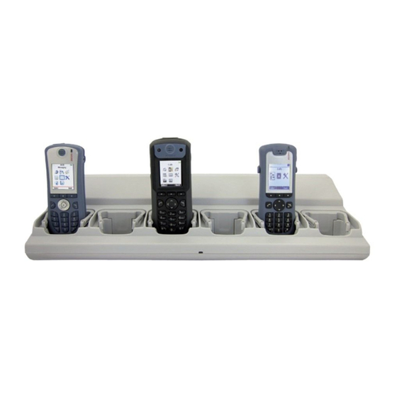
Page 5: Technical Solution
INSTALLATION AND OPERATION MANUAL CR3 CR5, and CR7 Charging Racks Introduction Figure 1. Charging Rack on the example of CR7- AAAA Supply voltage: 100-240VAC/0.7A 50/60 Hz Building fuse for fixed installation: 10 A max The USB port on the Advanced Charging Rack is used to connect the Charging Rack to a Device Manager, or to a PC running the Portable Device Manager (PDM). -
Page 6: Interfaces
INSTALLATION AND OPERATION MANUAL CR3 CR5, and CR7 Charging Racks Introduction Model Charger functionality Advanced Charging Rack — Charging of the handset battery. — Provide a means for software and parameter update of handsets. Basic Charging Rack — Charging of the handset battery. -
Page 7: Regulatory Compliance Statements (Eu And Efta Only)
This equipment is in compliance with the essential requirements and other relevant provisions of EMC Directive 2014/30/EU, LVD Directive 2014/35/EU and of Directive 2015/863 (RoHS3) amending 2011/65/EU. The complete Declaration of Conformity is found at https://www.ascom-ws.com/doc. The product is marked with... -
Page 8: Charging Rack Installation
INSTALLATION AND OPERATION MANUAL Charging Rack Installation CR3 CR5, and CR7 Charging Racks Charging Rack Installation General The unit shall be installed by authorized personnel only. • The units shall be placed in a dry environment with a temperature range from +5° C up to + 40° C (41° F to 104°... -
Page 9: Placing On A Table
INSTALLATION AND OPERATION MANUAL CR3 CR5, and CR7 Charging Racks Charging Rack Installation Table 3 Example of plug and screw dimensions Wall material Plug length Screw diameter Single plasterboard Thorsman TP1 3.5 – 5 mm Double plasterboard Thorsman TP2 3.5 – 5 mm... -
Page 10: Wall Mounting
INSTALLATION AND OPERATION MANUAL Charging Rack Installation CR3 CR5, and CR7 Charging Racks Figure 3. Charging Rack with table adapters on the example of CR7- AAAA Wall Mounting Charging Rack shall not be mounted higher than 2000 mm. Follow these steps when mounting a Charging Rack to a wall: First, make an outline of how the Charging Racks are to be placed. - Page 11 INSTALLATION AND OPERATION MANUAL CR3 CR5, and CR7 Charging Racks Charging Rack Installation Figure 5. Example of CR7- AAAA Charging Rack with IEC C14 connector and an extension cord with an IEC C13 connector For the Advanced Charging Rack, connect the communication cable when required.
- Page 12 INSTALLATION AND OPERATION MANUAL Charging Rack Installation CR3 CR5, and CR7 Charging Racks Figure 6. Examples of ways to mount Charging Racks Opening the Top Cover Open the top cover by first pressing on the sides of the top cover, then lifting it upwards.
- Page 13 INSTALLATION AND OPERATION MANUAL CR3 CR5, and CR7 Charging Racks Charging Rack Installation Table 4 Wiring color codes Load Also called Brown Black Active Line, Hot Blue White Black Neutral Return, Cold, Grounded connector Gr/Ye Green Green Earth Ground, Safety...
- Page 14 INSTALLATION AND OPERATION MANUAL Charging Rack Installation CR3 CR5, and CR7 Charging Racks Figure 8. The rectangular cover to be removed and changed Mount the cable support holder at the unused opening in the charger closer to the AC power source.
-
Page 15: Communication Cable Connection
INSTALLATION AND OPERATION MANUAL CR3 CR5, and CR7 Charging Racks Charging Rack Installation 10. Replace the top cover, see Figure 7. Opening the top cover of the Charging Rack, page Fasten the power cord to the wall depending on local regulations. -
Page 16: Software Installation
INSTALLATION AND OPERATION MANUAL Charging Rack Installation CR3 CR5, and CR7 Charging Racks The USB connection is used for connecting the Charging Rack directly to a PC or to a LAN for the purpose of upgrading or configuring the Charging Rack itself or handsets placed in the charger. -
Page 17: Charging Rack Configuration
INSTALLATION AND OPERATION MANUAL CR3 CR5, and CR7 Charging Racks Charging Rack Configuration Charging Rack Configuration This section is applicable for the Advanced Charging Rack only. Each Charging Rack need access to DHCP to receive an IP address automatically. If no DHCP is accessible it is possible to configure with PDM Windows Version. -
Page 18: Commissioning
INSTALLATION AND OPERATION MANUAL Commissioning CR3 CR5, and CR7 Charging Racks Commissioning The commissioning includes the following: • Installation test, see Installation Test, page • Charging • Communication with PDM or Device Manager Charging To verify that the charging works, do as follows: Check that the LED on the front of the charger(s) is lit. -
Page 19: Charger Operation
INSTALLATION AND OPERATION MANUAL CR3 CR5, and CR7 Charging Racks Charger Operation Charger Operation When the charger is connected to an external power supply, normal operation is done as follows: Handset Charging Connect the charger to the AC power supply. -
Page 20: Maintenance
INSTALLATION AND OPERATION MANUAL CR3 CR5, and CR7 Charging Racks Maintenance Maintenance Information in this section is applicable to the Advanced Charger Rack only. Operation when the Charger Rack is Connected to a PDM or Device Manager When the charger is connected the following additional operations can be done: •... - Page 21 INSTALLATION AND OPERATION MANUAL CR3 CR5, and CR7 Charging Racks Maintenance Amber, flashing (100 ms on, 800 ms off) Change phone indication during Easy Replacement. Red, fixed Software error. Service needed. Error indication during Easy Replacement. Put back Red, flashing (100 ms on, 800 ms off) old handset in charger.
-
Page 22: Troubleshooting
INSTALLATION AND OPERATION MANUAL Troubleshooting CR3 CR5, and CR7 Charging Racks Troubleshooting The LED is applicable to the Advanced Charger Rack only. For general LED indications, see 6.4 LED Indications, page Fault Solution Status LED on the charger is not lit. -
Page 23: Related Documents
Installation and Operation Manual, Portable Device Manager (PDM), Windows version, TD 92325EN User Manual, Device Manager, TD 92855EN Data Sheet, CR3 Charging Rack, TD 92628 EN Data Sheet, CR5 Charging Rack, TD 93053EN Data Sheet, CR7 Charging Rack, TD 93291EN... -
Page 24: Document History
Document updated to apply the i62 handset. See change bars for additional changes. 25 May 2011 Document updated to apply the CR3 for charging only. See change bars for more information. 13 February 2014 Clarified that “ErP Directive 2009/125/EC” only is applicable for CR3 (charging only) in 1.3 Regulatory Compliance... - Page 25 INSTALLATION AND OPERATION MANUAL CR3 CR5, and CR7 Charging Racks Document History 19 February 2019 General: Minor changes in the whole document and its structure have been made. New: Added information about CR7. New Compliance Statements have been included into 1.5 Regulatory Compliance Statements (USA and Canada only), page 4.
- Page 26 Ascom (Sweden) AB Grimbodalen 2 SE–417 49 Göteborg Sweden Phone +46 31 55 93 00 www.ascom.com...
Need help?
Do you have a question about the CR3 and is the answer not in the manual?
Questions and answers
Regarding the CR3 charger...The electrical supply is stated as 100volts to 240volt @ 0.7amp. What is the units power consumption? 70watts - 168watts ? Hand-set, what is the flat to fully charged time?
The power consumption for the ASCOM CR3 charger is up to 168 watts (calculated as 240V × 0.7A).
The charging time from flat to fully charged for the ASCOM CR3 handset is not provided.
This answer is automatically generated