
Related Manuals for Slee MICROTOME CUT 6062


Summary of Contents for Slee MICROTOME CUT 6062
- Page 1 O P E R A T I N G M A N U A L M I C R O T O M E C U T 6 0 6 2 FULLY-AUTOMATIC ROTARY MICROTOME D ES I GN & M A N UFACT UR I NG M A DE IN GE R M A NY...
-
Page 3: Table Of Contents
CONTENTS INTENDED USE _______________________________________________________ 5 SYMBOLS ____________________________________________________________ 5 SAFETY NOTES _______________________________________________________ 5 HAND WHEEL STOP FINGER PROTECTION GUARD ELECTRICAL CONNECTIONS EMERGENCY SWITCH MOTORIZED OPERATION WORKING WITH KNIVES AND DISPOSABLE BLADES COMPONENTS ______________________________________________________ 11 MAGNIFIER WITH ILLUMINATION, DIMMABLE (OPTIONAL) SPECIFICATIONS _____________________________________________________ 15 UNPACKING AND INSTALLATION _____________________________________ 17 UNPACKING THE DEVICE INSTALLATION... - Page 4 7.14 ROCKING MODUS 7.15 ADJUSTMENT OF RETRACTION DURING THE UPWARD MOVEMENT 7.16 SECTION COUNTER / SECTION SUM / REMAINING TRAVEL INDICATION 7.17 DISPLAY CONTRAST SETTINGS 7.18 SETTING OF CUTTING SPEED 7.19 SETTING OF TRIMMING SPEED 7.20 SETTING OF CUTTING MODE 7.21 PROGRAMMING AUTOMATIC CUTTING 7.22 OVERVIEW KEY COMBINATIONS EXTERNAL CONTROL PANEL CUT 6062 ________________________________ 45...
-
Page 5: Intended Use
1 INTENDED USE The rotary microtome CUT 6062 is intended for cutting thin sections of soft paraffin-embedded and harder specimens for professional use in routine and research laboratories in the fields of biology, medicine and industry. The system of specimen advance operates very reliable from 0.5 to 100 µm. The quality of cutting of this microtome is increased by the automatic retraction during the upstroke of the specimen, which avoids rubbing on the disposable blades or microtome knives. -
Page 6: Hand Wheel Stop
MAGNIFIER WITH LIGHTING (OPTIONAL) Risk of glare and injury! Never look into the sun or any other bright light source with optical devices! Do not look directly into the light source. Fire hazard! Lenses in optical devices can cause considerable damage due to the "burn- ing glass effect"... - Page 7 3.1.2 HANDWHEEL STOP WITH BRAKE ON THE BASE (OPTIONAL) Always use the finger protection guard with the knife- / blade holder and put hand wheel in stop position • before working with the knife or specimen, • before changing the specimen, •...
-
Page 8: Finger Protection Guard
3.2 FINGER PROTECTION GUARD Use the finger protection guard for the blade and knife holder as well as the handwheel stop always Finger protection guard released • before you start any work with the knife or spec- imen, • before changing the specimen, •... -
Page 9: Electrical Connections
3.3 ELECTRICAL CONNECTIONS Before connecting any electrical units, the device must be switched off. Electrical connections are attached at the backside of the microtome. Further on the name plate is located here (pos. Following connections are available depending on the mi- crotome type: 2: External Control Panel 3: Footswitch... -
Page 10: Emergency Switch
3.4 EMERGENCY SWITCH By pressing the red emergency switch an emergency stop is activated. The cutting motor stops immediately. For deactivating the emergency stop it has to be turned, then it moves automatically back into the original position. The device switches on again automatically. The motor re- mains switched off for safety reasons and must be switched on and started again for operation. -
Page 11: Components
4 COMPONENTS Slee rotary microtomes are provided with the following standard components: CUT 6062, #10080001 Specimen orientation • Universal cassette clamp, orientable, alternatively standard specimen clamp, orientable • 3-component knife holder, can be used for low profile blades as well as high profile blades •... -
Page 12: Magnifier With Illumination, Dimmable (Optional)
4.1 MAGNIFIER WITH ILLUMINATION, DIMMABLE (OPTIONAL) Mounting: The ring magnifier with illumination can easily be at- tached to the side of the microtome's base plate. 2 M5x12 countersunk screws (supplied) are screwed into the base plate from below. Manual_CUT_6062_2021-10-008.00_EN.docx... - Page 13 Switching on / off: The light can be switched on and off via the sensor switch on the light head. Switching on: Touch the sensor for a brief moment -> the light will be switched on (switch-on value is the last dim- ming value).
- Page 14 Specifications magnifier with illumination: Protection class Protection type IP 20 Operating mode Continuous operation Technical safety check EN 60 598-1 Light head ca. Ø 122 x 13 mm Magnifier 6.0 dpt. approx. Ø 72 Rated voltage 100 - 240 V AC Frequency range 50/60 Hz Power consumption...
-
Page 15: Specifications
5 SPECIFICATIONS Nominal supply voltage 100 - 240 V + / -10 % Nominal frequency 50/60 Hz Power draw 120 VA Protective class (1) Power fuses 2 x T 1,6 A Pollution degree (1) Overvoltage installation category Maximum heat emission 120 J / s Operating temperature range +10 to +35 °C... - Page 16 Specimen orientation, z-axis 360° Section counter Strokes / Distance Dimensions [width x depth x height] 520 mm x 600 mm x 325 mm incl. handwheel and waste tray Weight without accessories 34 kg (1) According to IEC 1010, EN 61010 Manual_CUT_6062_2021-10-008.00_EN.docx...
-
Page 17: Unpacking And Installation
6 UNPACKING AND INSTALLATION 6.1 UNPACKING THE DEVICE Remove the upper wooden cover. Remove the upper supporting foams. Lift the device out of the wooden transportation case. Grasp the device underneath the base plate from the rear and front as shown in the figure below. Do not transport the device by holding it on the hand wheel shaft, the object head, the cover or the tray. -
Page 18: Operation Of Cut 6062
7 OPERATION OF CUT 6062 7.1 INSERTION OF SPECIMEN IN STANDARD SPECIMEN CLAMP Turn the handwheel to the highest position and activate the handwheel lock (see chapter 3.1) and the finger guard. Loosen the standard specimen clamp by turning the fixing screw counterclockwise. -
Page 19: Insertion Of Specimen In Universal Cassette Clamp
7.2 INSERTION OF SPECIMEN IN UNIVERSAL CASSETTE CLAMP Turn hand wheel to its highest position and activate the hand wheel lock. Activate finger protection guard. Open cassette fixation by pulling the fixation lever. Insert / remove cassette. Object fixation will go back into fixation position automati- cally. -
Page 20: Specimen Orientation Adjustment
7.3 SPECIMEN ORIENTATION ADJUSTMENT Turn hand wheel to its highest position and activate the hand wheel stop (see chapter 3.1). For orientation of the specimen, open the fixing lever on the right side of the orientation. For upward and downward orientation use the upper ori- entation wheel (see fig.). -
Page 21: Exchanging The Clamp Type
7.4 EXCHANGING THE CLAMP TYPE For exchanging the universal cassette clamp with specimen orientation with the standard specimen clamp (fixed), please proceed as follows: Move the universal cassette clamp to the upper position and fix the hand wheel by pressing the brake lever. Pull out the right handle of the specimen orientation to re- lease the universal cassette clamp out of the system. - Page 22 Disassemble the specimen orientation. Disassemble the standard specimen clamp to get access to the center screw – M8 x 50 mm. Install the basic part of the standard specimen clamp and fix it with the Allen screw. Manual_CUT_6062_2021-10-008.00_EN.docx...
- Page 23 Install the spindle, the washer and the knob. Manual_CUT_6062_2021-10-008.00_EN.docx...
- Page 24 To replace the universal cassette clamp with specimen orientation with the standard specimen clamp with specimen orien- tation, please proceed as follows: Move the universal cassette clamp to the upper position and fix the hand wheel by pressing the brake lever. Pull out the right handle of the specimen orientation to release the universal cassette clamp out of the system.
- Page 25 Install the right handle of the specimen orientation to fix the standard clamp. Manual_CUT_6062_2021-10-008.00_EN.docx...
-
Page 26: Insertion And Orientation Of Microtome Knives
7.5 INSERTION AND ORIENTATION OF MICROTOME KNIVES Turn the handwheel to the highest position and activate the handwheel lock (see chapter 3.1). Remove finger protection guard on the right side of the knife holder. Loosen the knife fixation by turning the two black screws counter clockwise (see fig.). -
Page 27: Insertion And Orientation Of Disposable Blades
7.6 INSERTION AND ORIENTATION OF DISPOSABLE BLADES Turn the handwheel to the highest position and activate the handwheel lock (see chapter 3.1). Release the finger guard. Release the blade clamping lever on the left side of the blade holder by turning it counterclockwise. Remove the old blade or insert a new blade (see fig.). - Page 28 Horizontal orientation of the blade For adjustment of cutting area of the blade, the blade holder can be moved to the left or right. To do so, release the lever on the lower right side of the swivel piece by turning it counterclockwise (see fig.). Move the knife holder to the left or right.
- Page 29 Adjusting the sledge clamping Remove the screw with Allen key size 2,5 (pos. Removing washers makes clamping tighter. Add- ing washers loosens clamping. Tighten the screw (pos. 1) and test the clamping by assembling the blade holder. Adjusting the blade clamping Remove away the blade clamping plate (pos.
- Page 30 Modification from low to high blades Before any manipulation of the blade holder remove the blade! The first picture shows the low-profile configuration, un- derneath the low-profile configuration without the blade and the third picture shows the high-profile configuration. To change from low profile to high profile configuration the two screws (pos.
- Page 31 Changing the lever to the other side - blade clamp Loosen the screw (located on bottom side of lat- eral sledge) with Allen key (see fig., marked with red circle no. 1). Take the lever out of the sledge and put it into the hole from the other side.
-
Page 32: Approach To Specimen
7.7 APPROACH TO SPECIMEN Turn the handwheel to the highest position and acti- vate the handwheel lock (see chapter 3.1). Loosen the knife or blade holder base by turning the left lever counter clockwise (see fig.). Loosening of knife or blade holder base fixation and move- ment towards specimen Move the blade holder base inside the guiding rail to- wards or away from the specimen (see fig.). -
Page 33: Specimen Feed Memory
7.8 SPECIMEN FEED MEMORY CUT 6062 is equipped with a specimen feed memory that stores two independent positions of the specimen. The LED on the upper right of the control panel will indicate which memory position is currently active. To select the other memory position press twice quickly. -
Page 34: Manual Cutting
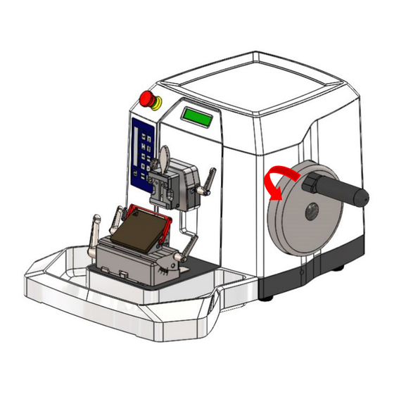
7.11 MANUAL CUTTING Release hand wheel stop (see chapter 3.1). Remove the finger guard if necessary. Turn the handwheel on the right side of the device evenly clockwise. A counter clockwise movement of the hand wheel will also result in cutting and the specimen is gradually brought closer to the blade. -
Page 35: Adjustment Of Trimming
7.12 ADJUSTMENT OF TRIMMING 30 µm TRIM R 5 µ The display indicates the current setting for the trimming mode (e. g. 30 µm in this example). 0000 n To change the trimming settings, press continuously and press increase or decrease the value. To return to the cutting mode, please press the key again. -
Page 36: Adjustment Of Retraction During The Upward Movement
7.15 ADJUSTMENT OF RETRACTION DURING THE UPWARD MOVEMENT 7 µm R 5 µ The display indicates the current setting for the retraction of the specimen upon upward movement (e. g. 5 µm in this example). 0000 n To change the retraction setting, press at the same time and , to increase or decrease the value. -
Page 37: Section Counter / Section Sum / Remaining Travel Indication
7.16 SECTION COUNTER / SECTION SUM / REMAINING TRAVEL INDICATION 7 µm R 5 µ The model CUT 6062 allows optional display of different parameters in the lower left display area. These are the number of the performed sections, the section sum 0015 n or the remaining travel. -
Page 38: Setting Of Cutting Speed
7.18 SETTING OF CUTTING SPEED The control of the cutting motor is by means of a slider on the left-hand side control panel. LED lights will display the current speed settings. The speed indicated is always the cutting speed (downward stroke), whereas the upward stroke is automatically calculated by the system software. -
Page 39: Setting Of Trimming Speed
7.19 SETTING OF TRIMMING SPEED The control of the cutting motor is by means of a slider on the left-hand side control panel. If the TRIM mode is acti- vated, LED lights will display the current speed settings for this mode. The speed indicated is always the cutting speed (downward stroke), whereas the upward stroke is automat- ically calculated by the system software. -
Page 40: Setting Of Cutting Mode
7.20 SETTING OF CUTTING MODE 7 µm R 5 µ For setting of cutting modes, press to activate the motor. 0000 n 7 µm R 5 µ The display will indicate the cutting mode and the cutting speed. 0000 n SING 50 mm/s 7 µm... - Page 41 Single cut – SING 7 µm R 5 µ In this mode, the cutting motor is started by pressing or by pressing the foot switch and will perform a cutting motion. The sample is stopped 0000 n SING 70 mm/s in the upper position.
-
Page 42: Programming Automatic Cutting
7.21 PROGRAMMING AUTOMATIC CUTTING 7 µm R 5 µ It is possible to preset the number of strokes which should be performed in the modes CONT and WIND. If one of those 2 modes are activated, this presetting will P 005 be activated by simultaneously pressing the buttons The preset number of cuts will be shown in the display. -
Page 43: Overview Key Combinations
7.22 OVERVIEW KEY COMBINATIONS 7.22.1 Operation via keyboard(s) Keyboard shortcuts at power-on (for configuration) TRIM/CUT TRIM/CUT switchover latching / momentary SLOW Setting feed rate for SLOW Retraction limitation on / off INFO/RESET+MEM Set all settings to factory defaults 7.22.2 Key combinations during operation TRIM/CUT+SLOW+PLUS Display service cut counter MODE+TRIM/CUT+PLUS/MINUS... - Page 44 7.22.4 Long keystrokes INFO/RESET (2 s) Reset cut counter MEM (2 s) Save current position in active position memory (confirmation: both position LEDs go off) REV, FWD, SLOW Direct movement of specimen holder (as long as key is pressed), while SLOW key is pressed fast "typing"...
-
Page 45: External Control Panel Cut 6062
8 EXTERNAL CONTROL PANEL CUT 6062 Before connecting any electrical units, the device must be switched off. 8.1 EXTERNAL CONTROL PANEL CUT 6062 To provide a more comfortable usage of the microtome the optional external control panels can be used for CUT 6062. The control panel is equipped with a connection cable to the microtome with a length of 1.80 m so the placement of the control panel can be arranged individually. -
Page 46: Functional Overview Of User Interface
8.2 FUNCTIONAL OVERVIEW OF USER INTERFACE Manual_CUT_6062_2021-10-008.00_EN.docx... -
Page 47: Cleaning And Maintenance
Remove section waste from the waste tray. Please use supplied dust cover when device is not in use. Weekly Cleaning of blade holder. Yearly Annual inspection (performed by authorized Slee service technician) • Check of all functions • Lubricating of movable parts •... -
Page 48: Service
If it is necessary to return the device, it must be cleaned and disinfected before delivery. It must be returned in its original packing. If the device or parts thereof are sent back in a dirty or non-disinfected condition, SLEE medical GmbH reserves the right to return the parts to the debit of the customer. -
Page 49: Optional Accessories
11 OPTIONAL ACCESSORIES aquatec system #10090056 MTR Bench top quick-freezing unit #10110000 Magnifier with illumination #10090060 External control panel CUT 6062 #10090051 Disposable blade holder TC65 (for tungsten carbide blades) #10090041 Tungsten carbide blade (1 pc.) #28406000 Glass knife holder (for triangle glass knives) #10090014 Segment arc incl. -
Page 50: Warranty
12 WARRANTY SLEE medical GmbH guarantees that the product delivered has been subjected to a comprehensive quality control procedure, and that the product is faultless and complies with all technical specifications and / or agreed characteristics warrant-ed. SLEE medical GmbH guarantees that the device is manufactured under an ISO 9001:2015 and ISO 13485:2016 quality management system. - Page 51 Notes Manual_CUT_6062_2021-10-008.00_EN.docx...
- Page 52 SLEE medical GmbH • Am Neuberg 14 55268 Nieder-Olm • Germany www.slee.de T: +49 (0) 6136 76997-0 E: mail@slee.de www.slee.de YouTube LinkedIn Instagram INS1000-30GB ∙ Manual_CUT_6062_2021-10-008.00_EN...
Need help?
Do you have a question about the MICROTOME CUT 6062 and is the answer not in the manual?
Questions and answers