
Related Manuals for overhoff 357RM


Summary of Contents for overhoff 357RM
- Page 1 OPERATION/MAINTENANCE MANUAL TRITIUM MONITOR MODEL 357RM OVERHOFF TECHNOLOGY CORPORATION 1160 US ROUTE 50, MILFORD, OHIO, USA...
- Page 2 Operation and Maintenance Manual, Model 357RM Tritium Monitor, Serial No. 5075-76 REVISION INDEX Date Section/Page Details Appvd By 02-20-2019 Original Document...
-
Page 3: Table Of Contents
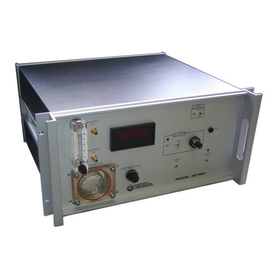
Tritium Monitor BETATEC Model 357 with dual 2 liter ionization chamber, single range, digital display, radon alpha pulse suppression, single alarm system TABLE OF CONTENTS FIGURE 1, FRONT AND REAR PANELS ..................1 GENERAL INFORMATION ....................2 1.1. INTRODUCTION 1.2. AVAILABLE CONFIGURATIONS 1.3. - Page 4 4.0. CALIBRATION…………..........…………………………..…………15 4.1. FIRST METHOD, TRITIUM GAS CALIBRATION…………………………………..16 4.2. SECOND METHOD, GAMMA CALIBRATION 4.2.1. CALIBRATION VERIFICATION USING A SMALL GAMMA CHECK SOURCE ...................... 17 4.3. THIRD MEHTOD - ELECTRICAL EQUIVALENCE METHOD GAS METHOD, PRACTICAL PROCEDURE 4.4.1. DIRECT GAMMA CALIBRATION ..............18 4.4.2.
-
Page 6: General Information
Therefore, ionization chambers will respond to X-rays and gamma radiation as well. To overcome this effect, Overhoff Technology Corporation (OTC) tritium monitors can be supplied with compensating ionization chambers. Here a second ionization chamber is used to cancel the effects of external radiation upon the measuring ionization chamber. -
Page 7: Features
1.3. FEATURES While the basic purpose of the OTC tritium monitor is to measure the presence and level of tritium (or other airborne radioisotopes) the monitors may be supplied with a number of user selected special features. Your particular instrument, which is described in this manual, has these special features. 1. -
Page 8: The Wall Effect
It must be remembered that the ionization chamber responds to the quantity of tritium present inside. This is to say that effects due to temperature and pressure may need to be accounted for. Even if a sample of gas is known to contain tritium at a certain concentration, i.e., parts per million or other, it must be remembered that the activity (amount per unit volume) is dependent upon temperature and pressure. -
Page 9: Discrimination Against Alpha Pulses
Consult the factory for further information, or for application engineering 1160 US Route 50, P. O. Box 182 Milford, OH 45150-9705, USA Telephone (513) 248-2400; Facsimile (513) 248-2402 sales@Overhoff.com; support@overhoff.com www.Overhoff.com... -
Page 10: Performance Specifications
1.8. PERFORMANCE SPECIFICATIONS The following specifications will apply when this instrument is used for the measurement of tritium 1.8.1. MEASUREMENT 1 – 19,999 μCi/m RANGES Tritium DISPLAY Digital Meter, 4 ½” digit LED ±10 % of reading, ±1 μCi/m ACCURACY , whichever is greater ±1 μCi/m STABILITY AND... -
Page 11: Flowmeter
1.8.4. FLOWMETER 0-10 LPM adjustable rotameter 1.8.5. DUST FILTER high efficiency 99.99% at 0.1 microns, respirator type filter cartridge Solberg Manufacturing Product No. HE04 1.8.6. PUMP long life continuous duty oscillating piston positive displacement pump. Medo Model VCO201E1 for 115VAC 1.8.7. -
Page 13: Equipment And Installation
2.0. EQUIPMENT AND INSTALLATION 2.1. EQUIPMENT SUPPLIED 1. Cabinet containing filter, flowmeter and pump, plus all associated electronics, displays and ionization chamber/electrometer assembly 2. Detachable AC line cord, 10ft (3m) long CAUTION: Do NOT replace the supply cord with an improperly rated one, for additional information, refer to the Safety Notice at the beginning of this manual 3. -
Page 14: Precaution, Sample Flow System
2.2.1. PRECAUTION, SAMPLE FLOW SYSTEM A high efficiency dust filter must always be installed at the input of the measuring ionization chamber. Failure to include a dust filter will cause debris build-up in the ion trap and the monitor will behave erratically. Monitors placed into lines carrying pure dust free process gases are an exception to the dust filter rule. -
Page 16: Instrument Architecture, Description
3.0. INSTRUMENT ARCHITECTURE, DESCRIPTION 3.1. GENERAL This section contains a simplified basic description of the functioning of the individual components of this monitor. The description is provided as background information for the user, engineer, or technician responsible for service and calibration. 3.2. -
Page 17: Circuit Description
3.3. CIRCUIT DESCRIPTION CAUTION: This instrument has not been designed for indiscriminate opening or disassembly of the internal parts. It contains highly sensitive semiconductors which are damaged by even the slightest electrostatic discharge. 3.3.1. IONIZATION CHAMBERS In its simplest form, an ionization chamber is an enclosed volume with two electrodes. Voltage is applied between the electrodes, generating an electric field which will segregate and collect electric charges which are created by nuclear events occurring inside the chambers. -
Page 18: Signal Processing Amplifier
3.3.3. SIGNAL PROCESSING AMPLIFIER The signal processing amplifier converts the output of the electrometer signal into a 0 - 10 V signal for driving the panel meter, the alarm system and remote signal outputs. Proprietary circuitry is used for the recognition and elimination of transient signals due to alpha pulses generated by radon decay or due to passage of high energy cosmic rays. -
Page 19: Calibration
4.0. CALIBRATION INTRODUCTION Calibration (or verification) of tritium monitors can be accomplished by three different methods. The object is to make sure that the instrument displays reading which correctly corresponds to the activity of the tritium laden gas stream passing through the ionization chamber. Each method has advantages and disadvantages. -
Page 20: First Method, Tritium Gas Calibration
4.1. FIRST METHOD, TRITIUM GAS CALIBRATION The first method involves the injection of tritium into the ionization chambers in an amount that will produce an accurately predictable concentration. The tritium monitor calibration potentiometer is then adjusted to make the measurement display coincide with the predicted gas concentration. In order to do this, one needs a source of tritium gas with a known activity and knowledge of effective volumes of ionization chambers and all other volumes involved. -
Page 21: Calibration Verification Using A Small Gamma Check Source
CAUTION: The ion current resulting from irradiation with gamma rays is a function of the TOTAL MASS inside the chamber. When performing gamma calibration, it is important to always note the ambient temperature and pressure as changes in these variables will alter the gamma response in accordance with normal gas laws. 4.2.1. -
Page 22: Direct Gamma Calibration
Calculating the activity produced by using the gas calibrator involves knowledge of the concentration of the contents of the tritium tank, quantity of tritium injected into the system, and the total volume of the system which includes all wetted volumes. This includes those of the entire ionization chamber system (inside chamber and ion trap), tubing or piping connections, pump volume, and any of the calibrator. -
Page 24: Evidence Of Malfunction, Periodic Calibration
Thus, knowing the voltage, and the resistance, it is simple to calculate the current, and to calculate the expected panel meter display. In order to perform this electrical calibration, the following steps may be performed. 1. Zero the monitor. Ω nominal value) to 2. -
Page 25: Repair And Troubleshooting
REPAIR AND TROUBLESHOOTING Repair of the tritium monitor is, in general, restricted to replacement of modules. The complete instrument or faulty modules should be returned to the factory (Overhoff Technology Corporation) for repair, after which they will be returned to the customer. -
Page 26: Mechanical
e. If available, attach spare ionization chamber assembly onto electrical connector to see if this corrects the problem. If so, replace the defective ionization chamber and recalibrate the instrument with the new chamber. Return the defective ionization chamber assembly to the factory for repair. If temporary replacement does not cure the problem, replace the main printed circuit board. -
Page 27: Maintenance
OVERHOFF TECHNOLOGY CORPORATION. Should it appear to be necessary to return the instrument to our factory, authorization for the return must be obtained from Overhoff Technology Corporation prior to shipping. In-freight charges will be borne by the customer. -
Page 28: Storage
7.0. STORAGE The equipment may be stored indefinitely in any storage place with the following environmental conditions: Temperature: -40º C - +60º C Humidity: 0 - 95 % R.H. Atmospheric: should be free of corrosive vapors or liquids During temporary or extended storage make sure that the gas ports to the ionization chambers and all electrical connectors be protected from moisture or contamination. -
Page 29: Warranty
8.0. WARRANTY All instruments built by Overhoff Technology Corporation are warranted to perform as claimed. Defective components or workmanship of the instrument will be corrected free of charge for parts and/or labor within a one year period from date of delivery. Non-performance of the instrument as a result of negligence on behalf of the customer is not covered by this warranty. -
Page 30: Drawings/Diagrams
DRAWINGS/DIAGRAMS DRAWING DESCRIPTION NUMBER 1020941-3922 Front Panel, Model 357RM Sheet 1 of 3 Rear Panel, Model 357RM 1020941-3922 Sheet 2 of 3 1020941-3922 Interior Layout, Model 357RM Sheet 3 of 3...
Need help?
Do you have a question about the 357RM and is the answer not in the manual?
Questions and answers