
Related Manuals for overhoff TASC-HTO-HT-C14


Summary of Contents for overhoff TASC-HTO-HT-C14
- Page 1 OPERATION/MAINTENANCE MANUAL CARBON 14 AND TRITIUM IN AIR SAMPLE COLLECTOR MODEL TASC-HTO-HT-C14 27 April 2017 REV. 0 OVERHOFF TECHNOLOGY CORPORATION 1160 US ROUTE 50, MILFORD, OHIO, USA...
-
Page 2: Table Of Contents
FIGURE 1, CARBON 14 ANALYSIS SET-UP DRAWING, TASC-HTO-HT-C14, FRONT & REAR PANEL DRAWING, TASC-HTO-HT-C14 AND SEPARATE C14 COLLECTION PANEL DRAWING, TASC-HTO-HT-C14, BLOCK DIAGRAM DRAWING, TASC-HTO-HT-C14, FLOW DIAGRAM, TRITIUM AND C14 COLLECTION DRAWING, TASC-HTO-HT-C14, FLOW DIAGRAM, TRITIUM ONLY COLLECTION DRAWING, TASC-HTO-HT-C14, WIRING DIAGRAM MANUFACTURERS DATA SHEETS... -
Page 3: Introduction
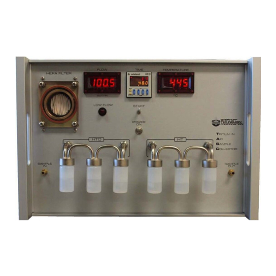
INTRODUCTION 1.1. GENERAL DESCRIPTION Overhoff Technology Corporation’s (OTC) Tritium and Carbon 14 in air sampler (TASC) is a simple and reliable line powered device for the passive sampling of very low levels of Carbon 14 and of tritium. This unit uses conventional techniques for collecting samples for any suitable length of time, as preferred by the user. -
Page 4: Specifications
2.0. SPECIFICATIONS - C SAMPLER μCi/cc for 7 day sample at 100±3 scc/min Sensitivity: 1 x 10 μCi/cc for 7 day sample at 100±3 scc/min 1 x 10 Air Flow Rate: 100±3 scc/min factory calibrated set point Flow Meter: Mass flow meter, 250 scc/minute full scale Air Flow Indicator: scc/min, Digital Display, 3½-digits, 0.1 to 199.9 Air Mover:... -
Page 5: Operation
3.0. OPERATING PRINCIPLES 3.1. SAMPLE COLLECTION The OTC TASC Sampling System operates by trapping radioactive material in vials containing absorbent material. To ensure virtually total collection, each main vial is succeeded by a second and third vial whose purpose is to trap any of the material which was missed by its predecessor. Six vials are therefore used to trap tritium oxide and elemental tritium. - Page 6 3.3. INTERNAL STRUCTURE The enclosure contains the following internal components. 1. Cooling fan. 2. Thermal oxidizer inside insulated housing. 3. Temperature Controller for the thermal oxidizer. 4. The airflow control P.C. board assembly (factory set to 100±3 scc/min). 5. The pneumatic components; sampling pump, vacuum reservoirs, mass flow meter and associated hoses.
-
Page 7: Use Of Instrument
4.0. USE OF INSTRUMENT 4.1. INSTALLATION AND SET-UP Install the instrument in a readily accessible area, protected from accidental damage, and from the elements if stationed out of doors. Supply 230VAC ±10%, 50-60Hz power (200 watts max.) to the instrument. Connect power and sampling tubing as required, ensure that the air sampling inlet lines do not unduly restrict air movement (flow) by verifying that the mass flow rate of 100±3 scc/minute is maintained at all times. - Page 8 4.2. OPERATING PROCEDURE 1. Power-up phase from a cold start: a. POWER toggle; move to up position (ON) Observe the following: b. Oxidizer temperature and Mass Flow Meter displays illuminated. c. Timer Module display is illuminated. The upper digit display is the current actual value, press reset to clear this value.
- Page 9 CAUTION: Do not unscrew a collecting vial while the pump is on. This could cause a sudden change in pressure or vacuum in certain parts of the pneumatic system which could cause liquid to be drawn from one of the other vials into the piping. Always make sure the pump is turned off and bubbling has completely stopped before removing a collection vial.
-
Page 10: Service
5.0. SERVICE Apart from the obvious periodic sample collection, which involves detaching the vials, no regular service maintenance is required. Periodic maintenance can be restricted to replacing the dust filter every two months (depending on its condition). The air sampling pump is a mechanical device, subject to wear. It can under optimum conditions, last two years or more, but, sooner or later it will wear out and will need to be replaced. -
Page 11: Analysis
6.0. ANALYSIS 6.1. TRITIUM ANALYSIS Analysis of the collected samples is carried out in a conventional manner, in the sense that it is assumed that the collection efficiency is either very close to 100 %, or at least reasonably well known. The analysis is therefore based on the assumption that the activity of 100 cc of air is accumulated every minute, thus, by reference to the observed lapsed time, it should be possible to derive the average air concentration by measuring the contents of the vials... - Page 12 6.2. CARBON 14 ANALYSIS The following procedure is used if Ascarite (solid NaOH with indicator) is used. The analysis of the C concentration is obtained by acidification of the entire sample of Ascarite media in a closed distillation system. Distillation releases CO which is captured downstream in a liquid scintillation cocktail in a countable form.
- Page 13 6. Fill the “addition funnel” about half way with fresh Ascarite, add some DRIERITE or MOLECULAR SIEVE (or other desiccant) to fill the funnel to the top. A plug of glass wool or cotton wool or similar should first be placed at the bottom of the funnel to prevent any of the solid material from entering the REFLUX flask.
- Page 14 DATA REDUCTION The formula for reducing raw data to concentrations of C in air streams is as follows: ⎛ ⎞ ⎛ ⎞ − ⎜ ⎟ ⎜ ⎜ ⎟ ⎟ ± ( )( ) ⎜ ( )( ) ⎟ ∈ ∈ ⎝...
-
Page 15: Miscellaneous Information
7.0. MISCELLANEOUS INFORMATION 1. The efficiency of the thermal oxidizer has been determined to exceed 95 % when at the nominal operating temperature of 455° - 475°C (851° - 887°F). 2. The use of cascaded collection vials ensures collection efficiency better than 99 % for tritium oxide. -
Page 16: Warranty
8.0. WARRANTY All instruments built by Overhoff Technology Corporation are warranted to perform as claimed. Defective components or workmanship of the instrument will be corrected free of charge for parts or labor within a period of one year form delivery. Nonperformance of the instrument as a result of negligence on behalf of the customer is not covered by this warranty. -
Page 17: Replacement Parts List
9.0. REPLACEMENT PARTS LIST PART NUMBER DESCRIPTION 3110SB-05W-B40-E00 Cooling Fan, Axial, 24VDC, 36 CFM 4YD95 Cooling Fan Inlet Guard with Filter 4YD92 Cooling Fan, Inlet Filter only H050D-11 Diaphragm Pump, brushless 24VDC, 1.5 LPM max MFM2120-BB-S2-Y Mass Flow meter 250 scc/min. full scale DMU-30DCV-1-DR-C Digital Display, 3½-Digit Voltmeter 2-114-N0674...
Need help?
Do you have a question about the TASC-HTO-HT-C14 and is the answer not in the manual?
Questions and answers