
Related Manuals for overhoff TRIATHALON-H3


Summary of Contents for overhoff TRIATHALON-H3
- Page 1 TRITIUM MONITOR TRIATHALON-H3 with optional Totalizer OPERATION AND MAINTENANCE MANUAL Revision 0 DATE: 20-Aug-2014 Generic Version OVERHOFF TECHNOLOGY CORPORATION 1160 US ROUTE 50, MILFORD, OHIO, USA...
-
Page 2: Table Of Contents
TABLE OF CONTENTS Section I. Introduction Page General Description Physical Description Features Performance Specifications Principle of Ion Chamber Measurments Figure – Front View Figure – Block Diagram Figure – Customer Connections Section II. Installation General Figure – Installation Diagram Equipment Checklist Storing, Handling, Unpacking Assembly Maintenance... -
Page 3: General Description
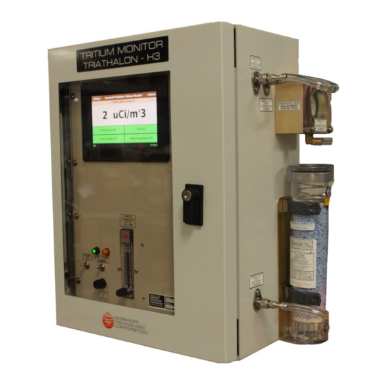
2.0. PHYSICAL DESCRIPTION The Model Triathalon-H3 is a single range, ionization chamber monitor for the measurement of tritium in a NEMA 4X enclosure suitable for permanent installation and for continuous duty. The enclosure has a hinged door with a polycarbonate window. Behind the hinged door is a front panel that is hinged so that it can be opened for servicing the various components inside. -
Page 4: Features
3.0. FEATURES While the basic purpose of the Overhoff Model Tiathalon-H3 tritium monitor is to measure the presence and level of tritium (HTO and HTO+HT), this particular instrument, described herein, has these special features. 1. Tritium Monitoring measurement range over four plus decades, using dual ionization chambers with a nominal volumes of 2 liters each. -
Page 5: Performance Specifications
4.0. PERFORMANCE SPECIFICATIONS The following specifications will apply when this is used for the measurement of tritium: 4.1. MEASUREMENT 1 – 19999 μCi/m Range Display LCD color touch screen ± 5 % of reading, ± L.S.D., whichever is greater Accuracy ±1μCi/m Stability and Drift long term (thirty days), ambient temperature conditions... - Page 6 4.3. IONIZATION CHAMBER VOLUME measuring: 1,600 cm total wetted: 2,000 cm ELECTRODES Solid wall on both sides GASKETS silicone rubber PRESSURE 0.1 to 2 atmospheres PORTS 3/16’’ I.D. Vinyl Tubing MATERIALS OF all wetted surfaces, stainless steel CONSTRUCTION 4.4. EXTERNAL SAMPLE 3/8’’...
-
Page 7: Principle Of Ion Chamber Measurments
To overcome this effect, Overhoff Technology Corporation (Overhoff) tritium monitors are sometimes supplied with compensating ionization chambers. Here a second ionization chamber is used to cancel the effects of external radiation. Overhoff tritium monitors are equipped with special circuitry to identify and reject ionization currents that are produced by decaying radon, or other airborne alpha emitting radioisotopes. - Page 8 5.3. RESPONSE OF IONIZATION CHAMBERS TO RADIATION The current generated in an ionization chamber is the result of collecting electrons generated from ionization of gas caused by occurrence of a nuclear event in the gas inside. The number of ions (magnitude of the current) is influenced by numerous factors like energy, physical nature and particle range.
- Page 9 Consult the factory for further information, or for application engineering at 1160 US Route 50, P.O. Box 182 Milford, OH 45150-9705, USA Telephone (513) 248-2400 Facsimile (513) 248-2402 Email: support@overhoff.com...
- Page 12 Model TRIATHALON‐H3 Customer Connections Terminal No. Description TB1‐0 Chassis Ground TB1‐1 From 115VAC Source (Neutral) TB1‐2 From 115VAC Source (Line) TB1‐8 Low Analog Output (Analog Common) TB1‐9 High Analog Output (0‐10V) Reset Total, switch closure TB1‐10 for 2 seconds minimum with TB1‐11 Reset Total, switch closure TB1‐11 for 2 seconds minimum with TB1‐10 TB601‐1 High Level Alarm No. 1, N.C. TB601‐2 High Level Alarm No. 1, N.O. TB601‐3 High Level Alarm No. 1, COM. TB601‐4 High Level Alarm No. 2, N.C. TB601‐5 High Level Alarm No. 2, N.O. TB601‐6 High Level Alarm No. 2, COM. TB601‐7 Alert Level Alarm No. 1, N.C. TB601‐8 Alert Level Alarm No. 1, N.O. TB601‐9 Alert Level Alarm No. 1, COM. TB601‐10 Alert Level Alarm No. 2, N.C. TB601‐11 Alert Level Alarm No. 2, N.O.
-
Page 13: Section Ii. Installation
4. Assembly Equipment Supplied The following equipment has been supplied by the manufacturer: 1 each, Tritium Monitor, Overhoff Technology Model Triathalon-H3 Monitor is enclosed in a fiberglass case ready for wall mounting Dimensions: 16.2’’ Wide x 20.3’’ High x 9.19’’ deep [41.2cm Wide x 51.5cm High x 23.4cm Deep]... -
Page 15: Equipment Checklist
Packaging and Delivery Procedures. The contents of the container(s) is as follows: Carton 1 of 1, 1 each, Tritium Monitor Overhoff Technology Model Triathalon-H3 3.0. STORAGE, HANDLING, UNPACKING This equipment has been packaged to protect it against damage while stored for extended periods of time in ordinary storage (dry warehouse) facilities. -
Page 16: Assembly
4.0. ASSEMBLY Assembly work consists of: 1. Attaching the enclosure to the wall using the appropriate anchors and tools as required. 2. Attaching conduit and wiring. 3. Attaching stainless steel tubing between the monitor and the existing pumping unit, as well as tubing to and from the sampling point for the pumping unit. ENCLOSURE AND PUMPING UNIT Pictorial installation instructions are enclosed with each unit. -
Page 17: Maintenance
Engineering assistance via telephone or facsimile, will be supplied by the manufacturer OVERHOFF TECHNOLOGY CORPORATION. Should it appear to be necessary to return the instrument to our factory, authorization for the return must be obtained from Overhoff Technology Corporation prior to shipping. In-freight charges will be borne by the customer. -
Page 18: Section Iii. Drawings And Schematics
SECTION III. DRAWINGS AND SCHEMATICS DRAWING DESCRIPTION NUMBER 1021345 Enclosure General Layout, Model Triathalon-H3 Sheet 1 of 2 1021345 Enclosure General Layout, Model Triathalon-H3 Sheet 2 of 2 1021345-PD Pneumatic Flow Diagram, Model Triathalon-H3... -
Page 22: Section Iv. Operation
OPERATION INSTRCTIONS Triathalon Tritium Monitor TABLE OF CONTENTS Page Startup Shutdown Main Screen About Screen Setup Screen Datalogging Software Upgrade Procedure Network Addressing 4-20 mA Connection... -
Page 23: Startup
The display will show t following sequence as the instrument initializes: An Overhoff Technology splash screen is displayed for 10 seconds A black screen with a blinking cursor in the upper left corner is displayed for 30 seconds A white screen divided into two buttons is displayed for 2 seconds... -
Page 24: Main Screen
OVERHOFF TECHNOLOGY www.overhoff.com mfmikula@overhoff.com 3. THE MAIN SCREEN <About> button: displays the model, software revision number, and contact information <Setup> button: allows setup parameters of the instrument to be changed “Tritium Level OK” button: this button will turn yellow or red if the tritium limits are exceeded. - Page 25 OVERHOFF TECHNOLOGY www.overhoff.com mfmikula@overhoff.com will be displayed on the bottom line of the display. It is very important that the power not be switched off while this message is being shown! The message is shown below. NOTE: Do not turn off the Triathalon when it is saving its settings! The “Saving Settings”...
-
Page 26: About Screen
OVERHOFF TECHNOLOGY www.overhoff.com mfmikula@overhoff.com Low flow alarm: Internal communications alarm: 4. THE ABOUT SCREEN Pressing the “About” button on the front panel will display this screen with contact information, and the version of software running in the Triathalon. -
Page 27: Setup Screen
OVERHOFF TECHNOLOGY www.overhoff.com mfmikula@overhoff.com 5. THE SETUP SCREEN The setup screen is shown when the <Setup> button on the main screen is pressed. There are 10 buttons that you can press on the setup screen. Each is explained below. 1. Set Limits – allows you to define the limit mode and values for the “high high tiritum” and “high tritium”... - Page 28 OVERHOFF TECHNOLOGY www.overhoff.com mfmikula@overhoff.com 1. Set Limits: There are two limits: a “High High” limit, and a “High” limit. Each limit has a separate relay which will close when the tritium limit value is exceeded. Both limits share the same button on the main screen.
- Page 29 OVERHOFF TECHNOLOGY www.overhoff.com mfmikula@overhoff.com 2. Units of Measure: Press the buttons in the right column to cycle through all the choices. Concentration Units and Volume Units should be set to one of the following: pCi/cc (or pCi/ml), nCi/L, uCi/m’3, mCi/m’3, Ci/m’3, MBq/m’3, kBq/L, Bq/cc (or Bq/ml), or MPCA and m’3.
- Page 30 OVERHOFF TECHNOLOGY www.overhoff.com mfmikula@overhoff.com 4. Communications: You can transmit datapoints to a program running on a remote computer Press the buttons in the right column to: (1) Turn transmitting on or off. (2,3) Specify the IP address and listening port of the remote computer.
- Page 31 (totalizing instruments only.) opy button: this writes the setup files, “otcmeas.cnf” and “otcconfig.cnf”, to the USB flash drive. This is only necessary in order to send these files to Overhoff to help diagnose problems.
- Page 32 OVERHOFF TECHNOLOGY www.overhoff.com mfmikula@overhoff.com 9. Date and Time This screen will allow you to set the computer’s internal clock to the correct time. Click “OK” after each step. Enter the: year, month (1 -12), day (1-31), hour (0-23), minute (0 -59), and second (0-59).
-
Page 33: Datalogging
OVERHOFF TECHNOLOGY www.overhoff.com mfmikula@overhoff.com 6. MORE ON DA TALOGGING The USB flash drive behav ior with this instrument’s computer is not as nice as you may be used to, on a Window s PC. For best results, follow these guidelines:... -
Page 34: Software Upgrade Procedure
.tgz. Do not unzip this file. This file should be placed UNZIPPED on one of the Overhoff USB flash drives in a folder named “install”. After this has been done, there are two ways to proceed. -
Page 35: Network Addressing
8. NETWORK ADDRESSING When communications are enabled, the Overhoff instrument will automatically send a data packet to a remote PC’s IP address and listening port at a time interval configured by the user. The Overhoff’s intern al computer’s IP Address is factory-set to 192.168.0.58. This can be changed y editing the file /etc /network/interfaces with the text editor “nano”:...
Need help?
Do you have a question about the TRIATHALON-H3 and is the answer not in the manual?
Questions and answers