Table of Contents
Advertisement
Quick Links
Advertisement
Table of Contents
Troubleshooting

Related Manuals for LG-Ericsson iPECS ES-4550G


Summary of Contents for LG-Ericsson iPECS ES-4550G
- Page 1 Installation Manual ES-4550G / ES-4526G Managed Layer 3 Stackable GE Switch...
- Page 3 N S T A L L A T I O N U I D E ES-4550G / ES-4526G ES-4550G M 48-P L3 S GE S ANAGED TACKABLE WITCH Layer 3 Stackable Gigabit Ethernet Switch with 44 10/100/1000BASE-T (RJ-45) Ports, 4 Gigabit Combination Ports (RJ-45/SFP), 2 10-Gigabit Extender Module Slots, and 2 Stacking Ports ES-4526G M...
- Page 5 OMPLIANCES AND AFETY TATEMENTS ES-4550G / ES-4526G FCC C LASS This device complies with Part 15 rules. Operation is subject to the following two conditions; This device may not cause harmful interference, and This device must accept any interference received, including interference that may cause undesired operation.
- Page 6 OMPLIANCES AND AFETY TATEMENTS ES-4550G / ES-4526G Cet appareil numérique respecte les limites de bruits radioélectriques applicables aux appareils numériques de Classe A prescrites dans la norme sur le matériel brouilleur: “Appareils Numériques,” NMB-003 édictée par le ministère des Communications. OREA LASS CE M...
- Page 7 OMPLIANCES AND AFETY TATEMENTS ES-4550G / ES-4526G AFETY OMPLIANCE SAFETY INSTRUCTION This product complies with and conforms to the following international Product Safety standards as applicable: Safety of Information Technology Equipment, IEC(EN) 60950-1, including ◆ all relevant national deviations as listed in Compliance with IEC for Electrical Equipment (IECEE) Safety of Information Technology Equipment, CAN/CSA-C22.2 No.
- Page 8 OMPLIANCES AND AFETY TATEMENTS ES-4550G / ES-4526G OWER AFETY Please read the following safety information carefully before installing the switch: Installation and removal of the unit must be carried out by qualified WARNING: personnel only. The unit must be connected to an earthed (grounded) outlet to comply with ◆...
- Page 9 OMPLIANCES AND AFETY TATEMENTS ES-4550G / ES-4526G Power Cord Set U.S.A. and Canada The cord set must be UL-approved and CSA certified. The minimum specifications for the flexible cord are: - No. 18 AWG - not longer than 2 meters, or 16 AWG. - Type SV or SJ - 3-conductor The cord set must have a rated current capacity of at least 10 A...
- Page 10 OMPLIANCES AND AFETY TATEMENTS ES-4550G / ES-4526G La prise secteur doit se trouver à proximité de l’appareil et son accès doit ◆ être facile. Vous ne pouvez mettre l’appareil hors circuit qu’en débranchant son cordon électrique au niveau de cette prise. L’appareil fonctionne à...
- Page 11 OMPLIANCES AND AFETY TATEMENTS ES-4550G / ES-4526G Bitte unbedingt vor dem Einbauen des Switches die folgenden Sicherheitsanweisungen durchlesen: Die Installation und der Ausbau des Geräts darf nur durch WARNUNG: Fachpersonal erfolgen. Das Gerät sollte nicht an eine ungeerdete Wechselstromsteckdose ◆ angeschlossen werden.
- Page 12 OMPLIANCES AND AFETY TATEMENTS ES-4550G / ES-4526G ARNINGS AND AUTIONARY ESSAGES This product does not contain any serviceable user parts. ARNING Installation and removal of the unit must be carried out by ARNING qualified personnel only. When connecting this device to a power outlet, connect the ARNING field ground lead on the tri-pole power plug to a valid earth ground line to prevent electrical hazards.
- Page 13 OMPLIANCES AND AFETY TATEMENTS ES-4550G / ES-4526G ND OF RODUCT This product is manufactured in such a way as to allow for the recovery and disposal of all included electrical components once the product has reached the end of its life. ANUFACTURING ATERIALS There are no hazardous nor ozone-depleting materials in this product.
- Page 14 OMPLIANCES AND AFETY TATEMENTS ES-4550G / ES-4526G – 14 –...
- Page 15 BOUT UIDE ES-4550G / ES-4526G URPOSE This guide details the hardware features of the switch, including the physical and performance-related characteristics, and how to install the switch. UDIENCE The guide is intended for use by network administrators who are responsible for installing and setting up network equipment;...
- Page 16 BOUT UIDE ES-4550G / ES-4526G EVISION ISTORY This section summarizes the changes in each revision of this guide. 2011 R PRIL EVISION This is the first revision of this guide. It is valid for the initial release for the standard version. –...
-
Page 17: Table Of Contents
ONTENTS ES-4550G / ES-4526G NTRODUCTION Overview Switch Architecture Network Management Options Description of Hardware Optional Media Extender Modules Features and Benifits ETWORK LANNING Introduction to Switching Application Examples Application Notes NSTALLING THE WITCH Selecting a Site Ethernet Cabling Equipment Checklist Mounting Connecting to a Power Source Connecting to the Console Port... - Page 18 ONTENTS ES-4550G / ES-4526G 10 Gbps Fiber Optic Connections Connectivity Rules Cable Labeling and Connection Records ROUBLESHOOTING Diagnosing Switch Indicators Power and Cooling Problems Installation In-Band Access Stack Troubleshooting ABLES Twisted-Pair Cable and Pin Assignments PECIFICATIONS Physical Characteristics Switch Features Management Features Standards Compliances...
- Page 19 ABLES ES-4550G / ES-4526G Table 1: Supported SFP Transceivers Table 2: Port Status LEDs Table 3: System Status LEDs Table 4: Supported XFP Transceivers Table 5: Supported SFP+ Transceivers Table 6: 10GBASE XFP Module LEDs Table 7: 10GBASE SFP+ Module LEDs Table 8: Serial Cable Wiring Table 9:...
- Page 20 ABLES ES-4550G / ES-4526G – 20 –...
- Page 21 IGURES ES-4550G / ES-4526G Figure 1: Front Panels Figure 2: Rear Panel Figure 3: 10 Gigabit Ethernet Module Slots Figure 4: Stacking Ports Figure 5: Port and System LEDs Figure 6: Power Supply Inlet Figure 7: Grounding Point Figure 8: Console Port Figure 9: Single Port 10GBASE Modules...
- Page 22 IGURES ES-4550G / ES-4526G Figure 30: Crossover Wiring – 22 –...
-
Page 23: Introduction
NTRODUCTION ES-4550G / ES-4526G VERVIEW The ES-4526G and ES-4550G Switches are intelligent multilayer switches (Layer 2, 3) with 24/48 10/100/1000BASE-T ports, four of which are combination ports that are shared with four SFP transceiver slots (see Figure 1, Ports 21-24/45- 48). -
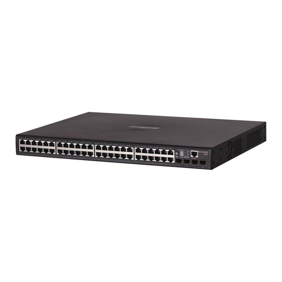
Page 24: Figure 1: Front Panels
| Introduction HAPTER Overview ES-4550G / ES-4526G Figure 1: Front Panels Port Status Indicators System Indicators ES-4526G 10/100/1000 Mbps RJ-45 Ports Mode Button SFP Ports Console Port System Indicators Console Port Mode Button ES-4550G 10/100/1000 Mbps RJ-45 SFP Ports Figure 2: Rear Panel RPS Inlet 10G Expansion Modules Power Inlet... -
Page 25: Switch Architecture
| Introduction HAPTER Switch Architecture ES-4550G / ES-4526G WITCH RCHITECTURE These Gigabit Ethernet switches employ a wire-speed, non-blocking switching fabric. This permits simultaneous wire-speed transport of multiple packets at low latency on all ports. The switches also feature full-duplex capability on all ports, which effectively doubles the bandwidth of each connection. -
Page 26: Description Of Hardware
| Introduction HAPTER Description of Hardware ES-4550G / ES-4526G ESCRIPTION OF ARDWARE 10/100/1000BASE-T P ORTS The switches contain 24/48 RJ-45 ports that operate at 10 Mbps or 100 Mbps, half or full duplex, or at 1000 Mbps, full duplex. Because all ports on these switches support automatic MDI/MDI-X operation, you can use straight-through cables for all network connections to PCs or servers, or to other switches or hubs. -
Page 27: Table 1: Supported Sfp Transceivers
| Introduction HAPTER Description of Hardware ES-4550G / ES-4526G Table 1: Supported SFP Transceivers Media Standard Fiber Diameter Wavelength (nm) Maximum Distance (microns) 1000BASE-SX 50/125 700 m 62.5/125 400 m 1000BASE-LX 50/125 1300 550 m 62.5/125 1300 550 m 9/125 1300 10 km 1000BASE-LH... -
Page 28: Figure 4: Stacking Ports
| Introduction HAPTER Description of Hardware ES-4550G / ES-4526G TACKING ORTS Each unit includes two stacking ports that provide a 48 Gbps high-speed serial stack backplane connection. Up to eight 24-port or 48-port switches can be connected together using optional stacking cables. Note that the 24-port and 48-port switches can be mixed in the same stack. -
Page 29: Table 2: Port Status Leds
| Introduction HAPTER Description of Hardware ES-4550G / ES-4526G Table 2: Port Status LEDs Condition Status Gigabit Ethernet Ports (Ports 1-24, or 1-48) Link/Activity/Speed On/Flashing Port has established a valid 10/100 Mbps network (Mode button not Amber connection. Flashing indicates activity. depressed) On/Flashing Port has established a valid 1000 Mbps network... - Page 30 | Introduction HAPTER Description of Hardware ES-4550G / ES-4526G Table 3: System Status LEDs Condition Status Stack Master Green Switch is the Master unit of the stack. State may include topology discovery, IP assignment, or normal operations. Flashing Green Switch is the Master unit of the stack, system is initializing.
-
Page 31: Figure 6: Power Supply Inlet
| Introduction HAPTER Description of Hardware ES-4550G / ES-4526G OWER UPPLY NLET There are two power sockets on the rear panel of each switch. The standard power socket is for the AC power cord. The socket labeled “RPS” is for the optional Redundant Power Supply (RPS). -
Page 32: Optional Media Extender Modules
| Introduction HAPTER Optional Media Extender Modules ES-4550G / ES-4526G ONSOLE This port is used to connect a console device to the switch through a serial cable. The console device can be a PC or workstation running a VT-100 terminal emulator, or a VT-100 terminal. -
Page 33: Table 4: Supported Xfp Transceivers
| Introduction HAPTER Optional Media Extender Modules ES-4550G / ES-4526G The module’s XFP slot supports standard 10 Gigabit Ethernet (10G) XFP transceivers. The 10GBASE transceivers operate at 10 Gbps full duplex with support for flow control. Due to a chipset limitation, the SFP+ transceivers will only operate at 10 Gbps, and cannot operate at lower speeds. -
Page 34: Features And Benifits
| Introduction HAPTER Features and Benifits ES-4550G / ES-4526G Table 7: 10GBASE SFP+ Module LEDs Condition Status Link/Activity On/Flashing Green Port has a valid link at 10 Gbps. Flashing indicates activity. The link is down. EATURES AND ENIFITS ONNECTIVITY 24 or 48 10/100/1000 Mbps ports for easy Gigabit Ethernet integration and ◆... - Page 35 | Introduction HAPTER Features and Benifits ES-4550G / ES-4526G ERFORMANCE Transparent bridging. ◆ Aggregate duplex bandwidth of up to 88 Gbps for the ES-4526G, or 136 ◆ Gbps for the ES-4550G. Switching table with a total of 16K MAC address entries and 8K IPv4 ◆...
- Page 36 | Introduction HAPTER Features and Benifits ES-4550G / ES-4526G – 36 –...
-
Page 37: Network Planning
ETWORK LANNING ES-4550G / ES-4526G NTRODUCTION TO WITCHING A network switch allows simultaneous transmission of multiple packets via non- crossbar switching. This means that it can partition a network more efficiently than bridges or routers. The switch has, therefore, been recognized as one of the most important building blocks for today’s networking technology. -
Page 38: Application Examples
| Network Planning HAPTER Application Examples ES-4550G / ES-4526G PPLICATION XAMPLES The switch is not only designed to segment your network, but also to provide a wide range of options in setting up network connections. Some typical applications are described below. OLLAPSED ACKBONE The Gigabit Ethernet Switches are an excellent choice for mixed Ethernet, Fast... -
Page 39: Figure 11: Network Aggregation Plan
| Network Planning HAPTER Application Examples ES-4550G / ES-4526G ETWORK GGREGATION With 24 or 48 parallel bridging ports (i.e., 24 or 48 distinct collision domains), a Gigabit switch stack can collapse a complex network down into a single efficient bridged node, increasing overall bandwidth and throughput. In the figure below, the 10/100/1000BASE-T ports in a stack of 48-port Gigabit Ethernet switches are providing 1000 Mbps connectivity through stackable switches. -
Page 40: Figure 12: Remote Connections With Fiber Cable
| Network Planning HAPTER Application Examples ES-4550G / ES-4526G Figure 12: Remote Connections with Fiber Cable Headquarters Warehouse 1000BASE-LX SMF (5 kilometers) 1000BASE-SX MMF (500 meters) Server Farm 1000BASE-LX SMF (5 kilometers) Remote Switch Remote Switch Research & Development 10/100/1000 Mbps Segments VLAN C AKING ONNECTIONS... -
Page 41: Figure 13: Maing Vlan Connections
| Network Planning HAPTER Application Examples ES-4550G / ES-4526G Figure 13: Maing VLAN Connections R&D VLAN 1 Tagged Ports Tagged Port Untagged Ports VLAN VLAN aware unaware switch Finance switch VLAN 2 Testing R&D Marketing Finance Testing VLAN 3 VLAN 1 VLAN 4 VLAN 2 VLAN 3... -
Page 42: Figure 14: Ip Routing For Unicast Traffic
| Network Planning HAPTER Application Examples ES-4550G / ES-4526G Figure 14: IP Routing for Unicast Traffic R&D IP Network 2 Testing IP Network 1 VLAN 1 VLAN 2 – 42 –... -
Page 43: Application Notes
| Network Planning HAPTER Application Notes ES-4550G / ES-4526G PPLICATION OTES Full-duplex operation only applies to point-to-point access (such as when a switch is attached to a workstation, server or another switch). When the switch is connected to a hub, both devices must operate in half-duplex mode. - Page 44 | Network Planning HAPTER Application Notes ES-4550G / ES-4526G – 44 –...
-
Page 45: Installing The Switch
NSTALLING THE WITCH ES-4550G / ES-4526G This chapter describes how to install the switches. ELECTING A Switch units can be mounted in a standard 19-inch equipment rack or on a flat surface. Be sure to follow the guidelines below when choosing a location. The site should: ◆... -
Page 46: Ethernet Cabling
| Installing the Switch HAPTER Ethernet Cabling ES-4550G / ES-4526G THERNET ABLING To ensure proper operation when installing the switch into a network, make sure that the current cables are suitable for 10BASE-T, 100BASE-TX or 1000BASE-T operation. Check the following criteria against the current installation of your network: Cable type: Unshielded twisted pair (UTP) or shielded twisted pair (STP) ◆... -
Page 47: Equipment Checklist
| Installing the Switch HAPTER Equipment Checklist ES-4550G / ES-4526G QUIPMENT HECKLIST After unpacking this switch, check the contents to be sure you have received all the components. Then, before beginning the installation, be sure you have all other necessary installation equipment. ACKAGE ONTENTS 24- or 48-port Gigabit Ethernet Switch (ES-4526G, or ES-4550G) -
Page 48: Mounting
| Installing the Switch HAPTER Mounting ES-4550G / ES-4526G OUNTING The switch can be mounted in a standard 19-inch equipment rack or on a desktop or shelf. Mounting instructions for each type of site follow. Stacking switches without enough space for airflow can AUTION damage to switch. -
Page 49: Figure 17: Attaching The Brackets
| Installing the Switch HAPTER Mounting ES-4550G / ES-4526G To rack-mount devices: Attach the brackets to the device using the screws provided in the Bracket Mounting Kit. Figure 17: Attaching the Brackets Mount the device in the rack, using four rack-mounting screws (not provided). -
Page 50: Figure 18: Installing The Switches In A Rack
| Installing the Switch HAPTER Mounting ES-4550G / ES-4526G Figure 18: Installing the Switches in a Rack If installing a single switch only, turn to "Connecting to a Power Source" on page 52 at the end of this chapter. If installing multiple switches, mount them in the rack, one below the other. –... -
Page 51: Figure 19: Attaching The Brackets
| Installing the Switch HAPTER Mounting ES-4550G / ES-4526G ESKTOP OR HELF OUNTING Attach the four adhesive feet to the bottom of the first switch. Figure 19: Attaching the Brackets Set the device on a flat surface near an AC power source, making sure there are at least two inches of space on all sides for proper air flow. -
Page 52: Connecting To A Power Source
| Installing the Switch HAPTER Connecting to a Power Source ES-4550G / ES-4526G ONNECTING TO A OWER OURCE To connect a switch to a power source: Insert the power cable plug directly into the AC inlet located at the back of the switch. -
Page 53: Connecting To The Console Port
| Installing the Switch HAPTER Connecting to the Console Port ES-4550G / ES-4526G ONNECTING TO THE ONSOLE This port is used to connect a console device to the switch through a serial cable. The console device can be a PC or workstation running a VT-100 terminal emulator, or a VT-100 terminal. -
Page 54: Installing An Optional Module Into The Switch
| Installing the Switch HAPTER Installing an Optional Module into the Switch ES-4550G / ES-4526G Parity—None ■ Stop bit—One ■ Data bits—8 ■ Flow control—none ■ NSTALLING AN PTIONAL ODULE INTO THE WITCH Figure 22: Installing an Optional Module The slide-in modules are hot-swappable, you do not need to power off the switch before installing or removing a module. -
Page 55: Installing An Optional Sfp Transceiver
| Installing the Switch HAPTER Installing an Optional SFP Transceiver ES-4550G / ES-4526G SFP T NSTALLING AN PTIONAL RANSCEIVER Figure 23: Installing an Optional SFP Transceiver These switches support 1000BASE-SX and 1000BASE-LX, and 1000BASE-LH SFP-compatible transceivers. To install an SFP transceiver, do the following:To install an SFP transceiver, do the following: Consider network and cabling requirements to select an appropriate SFP transceiver type. -
Page 56: Connecting Switches In A Stack
| Installing the Switch HAPTER Connecting Switches in a Stack ES-4550G / ES-4526G SFP transceivers are hot-swappable. The switch does not need to be powered off before installing or removing a transceiver. However, always first disconnect the network cable before removing a transceiver. -
Page 57: Figure 24: Making Stacking Connections
| Installing the Switch HAPTER Connecting Switches in a Stack ES-4550G / ES-4526G Figure 24: Making Stacking Connections Select the Master unit in the stack by pressing the Master button in on only one of the switches. Only one switch in the stack can operate as the Master, all other units operate in slave mode. - Page 58 | Installing the Switch HAPTER Connecting Switches in a Stack ES-4550G / ES-4526G When using line topology and a stack link failure occurs, the stack reboots and a Master unit is selected within each of the two stack segments. The Master unit will be either the unit with the Master button depressed or the unit with the lowest MAC address if the Master button is not depressed on any unit.
-
Page 59: Making Network Connections
AKING ETWORK ONNECTIONS ES-4550G / ES-4526G ONNECTING ETWORK EVICES These switches are designed to interconnect multiple segments (or collision domains). It can be connected to network cards in PCs and servers, as well as to hubs, switches or routers. It may also be connected to devices using optional XFP, SFP, or SFP+ transceivers. -
Page 60: Figure 25: Making Twisted-Pair Connections
| Making Network Connections HAPTER Twisted-Pair Devices ES-4550G / ES-4526G Figure 25: Making Twisted-Pair Connections If the device is a network card and the switch is in the wiring closet, attach the other end of the cable segment to a modular wall outlet that is connected to the wiring closet. -
Page 61: Network Wiring Connections
| Making Network Connections HAPTER Network Wiring Connections ES-4550G / ES-4526G ETWORK IRING ONNECTIONS Today, the punch-down block is an integral part of many of the newer equipment racks. It is actually part of the patch panel. Instructions for making connections in the wiring closet with this type of equipment follows. -
Page 62: Fiber Optic Sfp Devices
| Making Network Connections HAPTER Fiber Optic SFP Devices ES-4550G / ES-4526G Figure 26: Network Wiring Connections Equipment Rack Switch (side view) Punch-Down Block Patch Panel Wall SFP D IBER PTIC EVICES An optional Gigabit SFP (1000BASE-SX, 1000BASE-LX, 1000BASE-LH, or 100BASE-FX) transceiver can be used for a backbone connection between switches, or for connecting to a high-speed server. -
Page 63: Figure 27: Making Fiber Port Connections
| Making Network Connections HAPTER Fiber Optic SFP Devices ES-4550G / ES-4526G Warning: These switches use lasers to transmit signals over ARNING fiber optic cable. The lasers are compliant with the requirements of a Class 1 Laser Product and are inherently eye safe in normal operation. However, you should never look directly at a transmit port when it is powered on. -
Page 64: Gbps Fiber Optic Connections
| Making Network Connections HAPTER 10 Gbps Fiber Optic Connections ES-4550G / ES-4526G As a connection is made, check the Link LED on the switch corresponding to the port to be sure that the connection is valid. The 1000BASE-SX, 1000BASE-LX, 1000BASE-LH fiber optic ports operate at 1 Gbps, full duplex, with auto-negotiation of flow control. - Page 65 | Making Network Connections HAPTER 10 Gbps Fiber Optic Connections ES-4550G / ES-4526G Connect one end of the cable to the LC port on the switch and the other end to the LC port on the other device. Since LC connectors are keyed, the cable can be attached in only one orientation.
-
Page 66: Connectivity Rules
| Making Network Connections HAPTER Connectivity Rules ES-4550G / ES-4526G ONNECTIVITY ULES When adding hubs (repeaters) to your network, please follow the connectivity rules listed in the manuals for these products. However, note that because switches break up the path for connected devices into separate collision domains, you should not include the switch or connected cabling in your calculations for cascade length involving other devices. -
Page 67: Table 10: Maximum 10Gbase-Lr 10 Gigabit Ethernet Cable Length
| Making Network Connections HAPTER Connectivity Rules ES-4550G / ES-4526G Table 10: Maximum 10GBASE-LR 10 Gigabit Ethernet Cable Length Fiber Size Fiber Bandwidth Maximum Cable Length Connector 9/125 micron single- 10 km (6.2 miles) mode fiber Table 11: Maximum 10GBASE-ER 10 Gigabit Ethernet Cable Length Fiber Size Fiber Bandwidth Maximum Cable Length... -
Page 68: Table 15: Maximum 1000Base-Lh Gigabit Ethernet Cable Length
| Making Network Connections HAPTER Connectivity Rules ES-4550G / ES-4526G Table 15: Maximum 1000BASE-LH Gigabit Ethernet Cable Length Fiber Size Fiber Bandwidth Maximum Cable Length Connector 9/125 micron 2 m - 70 km single-mode fiber (7 ft - 43.5 miles) 100 M THERNET OLLISION... -
Page 69: Cable Labeling And Connection Records
| Making Network Connections HAPTER Cable Labeling and Connection Records ES-4550G / ES-4526G ABLE ABELING AND ONNECTION ECORDS When planning a network installation, it is essential to label the opposing ends of cables and to record where each cable is connected. Doing so will enable you to easily locate inter-connected devices, isolate faults and change your topology without need for unnecessary time consumption. - Page 70 | Making Network Connections HAPTER Cable Labeling and Connection Records ES-4550G / ES-4526G – 70 –...
-
Page 71: A Troubleshooting
ROUBLESHOOTING ES-4550G / ES-4526G IAGNOSING WITCH NDICATORS Table 19: Troubleshooting Chart Symptom Action PWR LED is Off ◆ Check connections between the switch, the power cord and the wall outlet. ◆ Contact your dealer for assistance. PWR LED is Amber ◆... -
Page 72: Power And Cooling Problems
| Troubleshooting PPENDIX Power and Cooling Problems ES-4550G / ES-4526G IAGNOSING OWER ROBLEMS WITH THE The Power and RPU LEDs work in combination to indicate power status as follows. Table 20: Power/RPU LEDs PWR LED RPU LED Status Green Green Internal power functioning normally;... -
Page 73: In-Band Access
| Troubleshooting PPENDIX In-Band Access ES-4550G / ES-4526G CCESS You can access the management agent in the switch from anywhere within the attached network using Telnet, a Web browser, or other network management software tools. However, you must first configure the switch with a valid IP address, subnet mask, and default gateway. - Page 74 | Troubleshooting PPENDIX Stack Troubleshooting ES-4550G / ES-4526G If any changes occur to a slave unit, such as unit failure or insertion of a new unit, operation of the other units in the stack are not affected. On the other hand, if the master unit fails, the unit with the lowest MAC address is elected as the new master.
-
Page 75: Cables
ABLES ES-4550G / ES-4526G WISTED ABLE AND SSIGNMENTS For 10/100BASE-TX connections, the twisted-pair cable must have two pairs of wires. For 1000BASE-T connections the twisted-pair cable must have four pairs of wires. Each wire pair is identified by two different colors. For example, one wire might be green and the other, green with white stripes. -
Page 76: Table 21: 10/100Base-Tx Mdi And Mdi-X Port Pinouts
| Cables PPENDIX Twisted-Pair Cable and Pin Assignments ES-4550G / ES-4526G 10BASE-T/100BASE-TX P SSIGNMENTS Use unshielded twisted-pair (UTP) or shielded twisted-pair (STP) cable for RJ-45 connections: 100-ohm Category 3 or better cable for 10 Mbps connections, or 100-ohm Category 5 or better cable for 100 Mbps connections. Also be sure that the length of any twisted-pair connection does not exceed 100 meters (328 feet). -
Page 77: Figure 29: Straight-Through Wiring
| Cables PPENDIX Twisted-Pair Cable and Pin Assignments ES-4550G / ES-4526G Figure 29: Straight-through Wiring EIA/TIA 568B RJ-45 Wiring Standard 10/100BASE-TX Straight-Through Cable White/Orange Stripe Orange White/Green Stripe End A End B Blue White/Blue Stripe Green White/Brown Stripe Brown ROSSOVER IRING If the twisted-pair cable is to join two ports and either both ports are labeled with an “X”... -
Page 78: Table 22: 1000Base-T Mdi And Mdi-X Port Pinouts
| Cables PPENDIX Twisted-Pair Cable and Pin Assignments ES-4550G / ES-4526G 1000BASE-T P SSIGNMENTS All 1000BASE-T ports support automatic MDI/MDI-X operation, so you can use straight-through cables for all network connections to PCs or servers, or to other switches or hubs. The table below shows the 1000BASE-T MDI and MDI-X port pinouts. -
Page 79: Table 23: 1000Base-T Mdi And Mdi-X Port Pinouts
| Cables PPENDIX Twisted-Pair Cable and Pin Assignments ES-4550G / ES-4526G 1000BASE-T DJUSTING XISTING ATEGORY ABLING TO If your existing Category 5 installation does not meet one of the test parameters for 1000BASE-T, there are basically three measures that can be applied to try and correct the problem: Replace any Category 5 patch cables with high-performance Category 5e or Category 6 cables. - Page 80 | Cables PPENDIX Twisted-Pair Cable and Pin Assignments ES-4550G / ES-4526G Table 23: 1000BASE-T MDI and MDI-X Port Pinouts ITU-T Description Application Standard G.654 1550-nm Loss-Minimized Extended long-haul applications. FiberSingle-mode, 9/125- Optimized for high-power micron core transmission in the 1500 to 1600-nm region, with low loss in the 1550-nm band.
-
Page 81: Specifications
PECIFICATIONS ES-4550G / ES-4526G HYSICAL HARACTERISTICS ORTS ES-4526G:20 10/100/1000BASE-T, with auto-negotiation 4 10/100/1000BASE-T shared with 4 SFP transceiver slots 2 10GBASE extender module slots for XFP or SFP+ transceivers Two slots for stacking transceivers ES-4550G:44 10/100/1000BASE-T, with auto-negotiation 4 10/100/1000BASE-T shared with 4 SFP transceiver slots 2 10GBASE extender module slots for XFP or SFP+ transceivers Two slots for stacking transceivers ETWORK... - Page 82 | Specifications PPENDIX Physical Characteristics ES-4550G / ES-4526G GGREGATE ANDWIDTH ES-4526G: 88 Gbps ES-4550G: 136 Gbps WITCHING ATABASE 16K MAC address entries, 1024 static MAC addresses; 2K IPv4 and 1K IPv6 entries in host table, 4K ARP entries, 256 IPv4 or 256 IPv6 entries in the IP routing table, 64 static IP routes, 32 IP interfaces;...
-
Page 83: Switch Features
| Specifications PPENDIX Switch Features ES-4550G / ES-4526G OWER UPPLY Internal, auto-ranging transformer: 100 to 240 VAC, 47 to 63 Hz External, supports connection for redundant power supply OWER ONSUMPTION ES-4526G: 66 Watts (without expansion modules) 80 Watts (with two expansion modules) ES-4550G: 100 Watts (without expansion modules) 130 Watts (with two expansion modules) AXIMUM... -
Page 84: Management Features
| Specifications PPENDIX Management Features ES-4550G / ES-4526G ANAGEMENT EATURES ANAGEMENT Web, Telnet, SSH, or SNMP manager ANAGEMENT RS-232 RJ-45 console port OFTWARE OADING TFTP in-band, or XModem out-of-band – 84 –... -
Page 85: Standards
| Specifications PPENDIX Standards ES-4550G / ES-4526G TANDARDS IEEE 802.3-2005 Ethernet, Fast Ethernet, Gigabit Ethernet Full-duplex flow control IEEE 802.3ae 10 Gigabit Ethernet IEEE 802.1D Spanning Tree Protocol IEEE 802.1w Rapid Spanning Tree Protocol IEEE 802.1s Multiple Spanning Tree Protocol IEEE 802.1Q Virtual LAN ISO/IEC 8802-3 CSMA/CD OMPLIANCES... -
Page 86: 10Gbase Extender Module (Xfp)
| Specifications PPENDIX 10GBASE Extender Module (XFP) ES-4550G / ES-4526G 10GBASE E (XFP) XTENDER ODULE ORTS 1 slot for 10GBASE XFP transceiver OMMUNINICATION PEED 10 Gbps OMMUNINCATION Full duplex ETWORK NTERFACE XFP Slot TANDARDS IEEE 802.3ae 10 Gigabit Ethernet 10GBASE E (SFP+) XTENDER ODULE... - Page 87 | Specifications PPENDIX 10GBASE Extender Module (SFP+) ES-4550G / ES-4526G ETWORK NTERFACE SFP+ Slot TANDARDS IEEE 802.3ae 10 Gigabit Ethernet – 87 –...
- Page 88 | Specifications PPENDIX 10GBASE Extender Module (SFP+) ES-4550G / ES-4526G – 88 –...
-
Page 89: Glossary
LOSSARY ES-4550G / ES-4526G 10BASE-T IEEE 802.3 specification for 10 Mbps Ethernet over two pairs of Category 3, 4, or 5 UTP cable. 100BASE-TX IEEE 802.3u specification for 100 Mbps Ethernet over two pairs of Category 5 UTP cable. 1000BASE-T IEEE 802.3ab specification for Gigabit Ethernet over 100-ohm Category 5, 5e or 6 twisted-pair cable (using all four wire pairs). - Page 90 LOSSARY ES-4550G / ES-4526G 10GBASE-ER IEEE 802.3ae specification for 10 Gigabit Ethernet over two strands of 9/125 micron core single-mode fiber cable. 10GBASE-LR IEEE 802.3ae specification for 10 Gigabit Ethernet over two strands of 9/125 micron core single-mode fiber cable. 10GBASE-SR IEEE 802.3ae specification for 10 Gigabit Ethernet over two strands of 62.5/125 micron core multimode fiber cable.
- Page 91 LOSSARY ES-4550G / ES-4526G TATION A workstation, server, or other device that does not forward traffic. THERNET A network communication system developed and standardized by DEC, Intel, and Xerox, using baseband transmission, CSMA/CD access, logical bus topology, and coaxial cable. The successor IEEE 802.3 standard provides for integration into the OSI model and extends the physical layer and media with repeaters and implementations that operate on fiber, thin coax and twisted-pair cable.
- Page 92 LOSSARY ES-4550G / ES-4526G IEEE 802.3 Defines CSMA/CD access method and physical layer specifications for 100BASE- TX Fast Ethernet. (Now incorporated in IEEE 802.3-2005.) IEEE 802.3 Defines Ethernet frame start/stop requests and timers used for flow control on full-duplex links. (Now incorporated in IEEE 802.3-2005.) IEEE 802.3 Defines CSMA/CD access method and physical layer specifications for 1000BASE Gigabit Ethernet.
- Page 93 LOSSARY ES-4550G / ES-4526G specified in units of MHz per km, which indicates the amount of bandwidth supported by the fiber for a one km distance. ETWORK IAMETER Wire distance between two end stations in the same collision domain. RJ-45 C ONNECTOR A connector for twisted-pair wiring.
- Page 94 LOSSARY ES-4550G / ES-4526G A VLAN serves as a logical workgroup with no physical barriers, allowing users to share information and resources as though located on the same LAN. – 94 –...
-
Page 95: Index
NDEX ES-4550G / ES-4526G UMERICS 10 Gbps connectivity rules electrical interference, avoiding 10 Mbps connectivity rules equipment checklist 100 Mbps connectivity rules Ethernet connectivity rules 1000 Mbps connectivity rules 1000BASE-LH fiber cable Lengths 1000BASE-LX fiber cable Lengths 1000BASE-SX fiber cable Lengths Fast Ethernet connectivity rules 1000BASE-T front panel of switch... - Page 96 NDEX ES-4550G / ES-4526G rear panel of switch RJ-45 port connections pinouts rubber foot pads, attaching SFP transceiver slots site selelction specifications compliances environmental power standards compliance IEEE surge suppressor, using switch architecture troubleshooting in-band access power and cooling problems twisted-pair connections –...
- Page 98 Printed in China MARCH / 2011 / ISSUE 1.0...
Need help?
Do you have a question about the iPECS ES-4550G and is the answer not in the manual?
Questions and answers