
Related Manuals for LG-Ericsson ES-2010GP


Summary of Contents for LG-Ericsson ES-2010GP
- Page 1 S E R U I D E Installation Manual ES-2010G Advanced Smart GE Switch ES-2010GP Advanced Smart GE POE Switch...
- Page 2 N S T A L L A T I O N ANUAL ES-2010G / ES-2010GP ES-2010G A 10-P GE S DVANCED MART WITCH Layer 2 Advanced Smart Switch with 8 10/100/1000BASE-T (RJ-45) Ports, and 2 Gigabit SFP Ports ES-2010GP A...
-
Page 3: Compliances And Safety Statements
OMPLIANCES AND AFETY TATEMENTS ES-2010G / ES-2010GP FCC C LASS This device complies with Part 15 rules. Operation is subject to the following two conditions; This device may not cause harmful interference, and This device must accept any interference received, including interference that may cause undesired operation. - Page 4 Amendment Directive 93/68/EEC. For the evaluation of the compliance with these Directives, the following standards were applied: The following declaration is for both the ES-2010G and the ES-2010GP model: RFI Emission: Limited class A according to: EN 55022:2006+A1: ◆...
- Page 5 OMPLIANCES ES-2010G / ES-2010GP The unit must be connected to an earthed (grounded) outlet to comply ◆ with international safety standards. Do not connect the unit to an A.C. outlet (power supply) without an ◆ earth (ground) connection. The appliance coupler (the connector to the unit and not the wall plug) ◆...
- Page 6 OMPLIANCES ES-2010G / ES-2010GP Power Cord Set Europe The supply plug must comply with CEE7/7 (“SCHUKO”). The mains cord must comply with IEC 60227 (designation 60227 IEC 52). IEC-320 receptacle. Veuillez lire à fond l'information de la sécurité suivante avant d'installer le Switch: AVERTISSEMENT: L’installation et la dépose de ce groupe doivent être...
- Page 7 OMPLIANCES ES-2010G / ES-2010GP Cordon électrique - Il doit être agréé dans le pays d’utilisation Etats-Unis et Le cordon doit avoir reçu l’homologation des UL et un Canada: certificat de la CSA. Les spécifications minimales pour un cable flexible sont AWG No. 18, ouAWG No. 16 pour un cable de longueur inférieure à...
- Page 8 OMPLIANCES ES-2010G / ES-2010GP Stromkabel. Dies muss von dem Land, in dem es benutzt wird geprüft werden: Schweiz Dieser Stromstecker muß die SEV/ASE 1011Bestimmungen einhalten. Europe Das Netzkabel muss mit IEC 60227 (IEC 60227 entsprechen Bezeichnung 52) Der Netzstecker muß die Norm CEE 7/7 erfüllen (”SCHUKO”).
- Page 9 OMPLIANCES ES-2010G / ES-2010GP ND OF RODUCT This product is manufactured in such a way as to allow for the recovery and disposal of all included electrical components once the product has reached the end of its life. ANUFACTURING ATERIALS There are no hazardous nor ozone-depleting materials in this product.
-
Page 10: About This Guide
BOUT UIDE ES-2010G / ES-2010GP This guide details the hardware features of the switches, including the URPOSE physical and performance-related characteristics, and how to install the switches. The guide is intended for use by network administrators who are UDIENCE responsible for installing and setting up network equipment; consequently, it assumes a basic working knowledge of LANs (Local Area Networks). -
Page 11: Table Of Contents
ONTENTS ES-2010G / ES-2010GP OMPLIANCES AND AFETY TATEMENTS BOUT UIDE ONTENTS IGURES ABLES NTRODUCTION Overview Switch Architecture Network Management Options Power-over-Ethernet Description of Hardware 10/100/1000BASE-T Ports SFP Transceiver Slots Port and System Status LEDs Power Supply Inlet Grounding Point Reset Button... - Page 12 ONTENTS ES-2010G / ES-2010GP Remote Connections with Fiber Cable Making VLAN Connections Application Notes NSTALLING THE WITCH Selecting a Site Ethernet Cabling Equipment Checklist Optional Rack-Mounting Equipment Mounting Rack Mounting Desktop or Shelf Mounting Connecting to a Power Source Installing an Optional SFP Transceiver...
- Page 13 ONTENTS ES-2010G / ES-2010GP Straight-Through Wiring Crossover Wiring 1000BASE-T Pin Assignments Fiber Standards ARDWARE PECIFICATIONS Physical Characteristics Switch Features Management Features Standards Compliances LOSSARY NDEX – 13 –...
-
Page 14: Figures
Figure 13: RJ-45 Connections Figure 14: Grounding Figure 15: Attaching the Brackets Figure 16: Installing the Switches in a Rack - ES-2010GP Figure 17: Installing the Switches in a Rack - ES-2010G Figure 18: Attaching the Adhesive Feet Figure 19: Power Inlet... -
Page 15: Tables
ABLES ES-2010G / ES-2010GP Table 1: Supported SFP Transceivers Table 2: Port Status LEDs Table 3: System Status LEDs Table 4: Maximum 1000BASE-T Gigabit Ethernet Cable Length Table 5: Maximum 1000BASE-SX Gigabit Ethernet Cable Lengths Table 6: Maximum 1000BASE-LX Gigabit Ethernet Cable Length... -
Page 16: Introduction
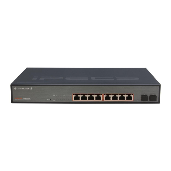
NTRODUCTION ES-2010G / ES-2010GP VERVIEW The ES-2010G and ES-2010GP are Gigabit Ethernet Layer 2 switches with 8 10/100/1000BASE-T ports, and 2 Small Form Factor Pluggable (SFP) transceiver slots, (see Figure 1 on page 16, Ports 9-10). The ES-2010GP also provides PoE power to connected devices. -
Page 17: Switch Architecture
| Introduction HAPTER Switch Architecture ES-2010G / ES-2010GP Figure 2: Rear Panels ES-2010G AC 100-240V~, 50-60Hz, 0.5A Grounding Point Power Inlet ES-2010GP AC 100-240V, 50~60Hz, 1.7A AC 100-240V, 50~60Hz, 1.7A Power Inlet Grounding Point WITCH RCHITECTURE These switches employ a wire-speed, non-blocking switching fabric. This permits simultaneous wire-speed transport of multiple packets at low latency on all ports. -
Page 18: Power-Over-Ethernet
OWER OVER THERNET All eight ports (1~8) of the ES-2010GP switch support the IEEE 802.3at standard that enables DC power to be supplied to attached devices using wires in the connecting Ethernet cable. The total PoE power delivered by all ports cannot exceed the 75 W power budget. -
Page 19: Port And System Status Leds
Figure 3: ES-2010G Port and System LEDs Port LEDs System LEDs Figure 4: ES-2010GP Port and System LEDs RJ-45 Port LEDs System LEDs SFP Port LEDs – 19 –... -
Page 20: Table 2: Port Status Leds
| Introduction HAPTER Description of Hardware ES-2010G / ES-2010GP Table 2: Port Status LEDs Condition Status Gigabit Ethernet Ports (Ports 1-8) Link/Activity/Speed On/Flashing Port has established a valid 10/100 Mbps network Amber connection. Flashing indicates activity. On/Flashing Port has established a valid 1000 Mbps network Green connection. -
Page 21: Power Supply Inlet
| Introduction HAPTER Description of Hardware ES-2010G / ES-2010GP There is one power inlet on the rear panel of the switch. The standard OWER UPPLY NLET power inlet is for the AC power cord. Figure 5: Power Supply Inlet AC 100-240V, 50~60Hz, 1.7A AC 100-240V, 50~60Hz, 1.7A... -
Page 22: Reset Button
| Introduction HAPTER Features and Benifits ES-2010G / ES-2010GP If you encounter any switch malfunctions, such as a hang or non- ESET UTTON recoverable error, you might want to reset the switch to its default configuration by pressing and holding the reset button for more than ten seconds. -
Page 23: Performance
| Introduction HAPTER Features and Benifits ES-2010G / ES-2010GP Transparent bridging. ERFORMANCE ◆ Aggregate duplex bandwidth of up to 20 Gbps. ◆ ◆ Switching table with a total of 8K MAC address entries. Provides store-and-forward switching. ◆ Supports wire-speed switching at Layer 2. -
Page 24: Network Planning
ETWORK LANNING ES-2010G / ES-2010GP NTRODUCTION WITCHING A network switch allows simultaneous transmission of multiple packets via non-crossbar switching. This means that it can partition a network more efficiently than bridges or routers. The switch has, therefore, been recognized as one of the most important building blocks for today’s networking technology. -
Page 25: Poe Connections
1 Gbps Full Duplex Full Duplex Full Duplex The ES-2010GP switch is an excellent choice for supplying power to ONNECTIONS connected PoE devices such as web cameras, IP telephones, or access points. The eight RJ-45 ports on the switch can provide up to 34.2 W of power to a connected device. -
Page 26: Network Aggregation Plan
| Network Planning HAPTER Application Examples ES-2010G / ES-2010GP Figure 9: Supplying PoE Power Reset DIAG Power-over-Ethernet Devices Access Point IP Telephone Web Camera With 10 parallel bridging ports (i.e., 10 distinct collision domains), these ETWORK switches can collapse a complex network down into a single efficient GGREGATION bridged node, increasing overall bandwidth and throughput. -
Page 27: Remote Connections With Fiber Cable
100BASE-FX (SMF) link up to 20 km. This allows the switches to serve as a collapsed backbone, providing direct connectivity for a widespread LAN. The figure below illustrates the ES-2010GP connecting multiple segments with fiber cable. Figure 11: Remote Connections with Fiber Cable... -
Page 28: Application Notes
| Network Planning HAPTER Application Notes ES-2010G / ES-2010GP Figure 12: Making VLAN Connections Reset DIAG R&D VLAN 1 Tagged Tagged Port Ports VLAN Untagged Ports unaware VLAN switch aware switch Finance VLAN 2 Testing R&D Marketing Finance Testing VLAN 3... -
Page 29: Installing The Switch
NSTALLING THE WITCH ES-2010G / ES-2010GP This chapter describes how to install the switches. ELECTING A ◆ The site should: be at the center of all the devices you want to link and near a power ■ outlet. be able to maintain its temperature within 0 to 50 °C (32 to 122 °F) ■... -
Page 30: Equipment Checklist
Then, before beginning the installation, be sure you have all other necessary installation equipment. Advanced Smart 10-Port GE Switch (ES-2010G), or ◆ Advanced Smart 10-Port GE PoE Switch (ES-2010GP) Four adhesive foot pads ◆ Grounding screw ◆... -
Page 31: Optional Rack-Mounting Equipment
| Installing the Switch HAPTER Optional Rack-Mounting Equipment ES-2010G / ES-2010GP PTIONAL OUNTING QUIPMENT If you plan to rack-mount the switches, be sure to have the following equipment available: Four mounting screws for each device you plan to install in a rack—... -
Page 32: Figure 15: Attaching The Brackets
Be sure to secure the lower rack-mounting screws first to prevent the brackets being bent by the weight of the switch. Figure 16: Installing the Switches in a Rack - ES-2010GP Figure 17: Installing the Switches in a Rack - ES-2010G If installing a single switch only, turn to “Connecting to a Power Source”... -
Page 33: Desktop Or Shelf Mounting
| Installing the Switch HAPTER Mounting ES-2010G / ES-2010GP If installing multiple switches, mount them in the rack, one below the other. Attach the four adhesive feet to the bottom of the first switch. ESKTOP OR HELF OUNTING Figure 18: Attaching the Adhesive Feet Set the device on a flat surface near an AC power source, making sure there are at least two inches of space on all sides for proper air flow. -
Page 34: Connecting To A Power Source
| Installing the Switch HAPTER Connecting to a Power Source ES-2010G / ES-2010GP ONNECTING TO A OWER OURCE To connect a switch to a power source: Insert the power cable plug directly into the AC inlet located at the back of the switch. -
Page 35: Installing An Optional Sfp Transceiver
| Installing the Switch HAPTER Installing an Optional SFP Transceiver ES-2010G / ES-2010GP SFP T NSTALLING AN PTIONAL RANSCEIVER Figure 20: Installing an Optional SFP Transceiver into a Slot These switches support 1000BASE-SX, 1000BASE-LX, 1000BASE-LH, and 100BASE-FX SFP-compatible transceivers. To install an SFP transceiver, do the following: Consider network and cabling requirements to select an appropriate SFP transceiver type. -
Page 36: Making Network Connections
Use Category 5, 5e, or 6 cable for 1000BASE-T connections, Category 5 or better for 100BASE-TX connections, and Category 3 or better for 10BASE-T connections. The ES-2010GP switch automatically detects a PoE-compliant device by its OWER OVER... -
Page 37: Cabling Guidelines
| Making Network Connections HAPTER Twisted-Pair Devices ES-2010G / ES-2010GP The RJ-45 ports on the switches support automatic MDI/MDI-X pinout ABLING UIDELINES configuration, so you can use standard straight-through twisted-pair cables to connect to any other network device (PCs, servers, switches, routers, or hubs). -
Page 38: Network Wiring Connections
| Making Network Connections HAPTER Twisted-Pair Devices ES-2010G / ES-2010GP Today, the punch-down block is an integral part of many of the newer ETWORK IRING equipment racks. Actually it is a part of the patch panel. Instructions for ONNECTIONS making connections in the wiring closet with this type of equipment follows. -
Page 39: Fiber Optic Sfp Devices
| Making Network Connections HAPTER Fiber Optic SFP Devices ES-2010G / ES-2010GP SFP D IBER PTIC EVICES An optional Gigabit SFP (1000BASE-SX, 1000BASE-LX, 1000BASE-LH, or 100BASE-FX) transceiver can be used for a backbone connection between switches, or for connecting to a high-speed server. -
Page 40: Connectivity Rules
| Making Network Connections HAPTER Connectivity Rules ES-2010G / ES-2010GP As a connection is made, check the Link LED on the switch corresponding to the port to be sure that the connection is valid. The 1000BASE-SX, 1000BASE-LX, 1000BASE-LH fiber optic ports operate at 1 Gbps, full duplex, with auto-negotiation of flow control. -
Page 41: 100 Mbps Fast Ethernet Collision Domain
| Making Network Connections HAPTER Cable Labeling and Connection Records ES-2010G / ES-2010GP Table 6: Maximum 1000BASE-LX Gigabit Ethernet Cable Length Fiber Size Fiber Bandwidth Maximum Cable Length Connector 9/125 micron single- 2 m - 10 km (7 ft - 6.2 miles) LC... - Page 42 | Making Network Connections HAPTER Cable Labeling and Connection Records ES-2010G / ES-2010GP Note the length of each cable and the maximum cable length supported ◆ by the switch ports. For ease of understanding, use a location-based key when assigning ◆...
-
Page 43: A Troubleshooting
ROUBLESHOOTING ES-2010G / ES-2010GP LED I IAGNOSING NDICATORS Table 11: LED Indicators LED Status Action PWR LED is Off ◆ Check connections between the switch, the power cord, and the wall outlet. ◆ Contact your dealer for assistance. DIAG LED is Flashing ◆... -
Page 44: In-Band Access
| Troubleshooting PPENDIX In-Band Access ES-2010G / ES-2010GP CCESS You can access the management agent in the switch from anywhere within the attached network using a web browser, or other network management software tools. However, you must first configure the switch with a valid IP address, subnet mask, and default gateway. -
Page 45: Ables And Pinouts
ABLES AND INOUTS ES-2010G / ES-2010GP WISTED ABLE SSIGNMENTS For 10/100BASE-TX connections, a twisted-pair cable must have two pairs of wires. For 1000BASE-T connections the twisted-pair cable must have four pairs of wires. Each wire pair is identified by two different colors. For example, one wire might be green and the other, green with white stripes. -
Page 46: Straight-Through Wiring
| Cables and Pinouts PPENDIX Twisted-Pair Cable Assignments ES-2010G / ES-2010GP Table 12: 10/100BASE-TX MDI and MDI-X Port Pinouts MDI Signal Name MDI-X Signal Name Transmit Data plus (TD+) Receive Data plus (RD+) Transmit Data minus (TD-) Receive Data minus (RD-) -
Page 47: 1000Base-T Pin Assignments
| Cables and Pinouts PPENDIX Twisted-Pair Cable Assignments ES-2010G / ES-2010GP Figure 26: Crossover Wiring EIA/TIA 568B RJ-45 Wiring Standard 10/100BASE-TX Crossover Cable White/Orange Stripe Orange White/Green Stripe End A End B Blue White/Blue Stripe Green White/Brown Stripe Brown All 1000BASE-T ports support automatic MDI/MDI-X operation, so you can... -
Page 48: Fiber Standards
| Cables and Pinouts PPENDIX Fiber Standards ES-2010G / ES-2010GP ABLE ESTING FOR XISTING ATEGORY ABLE Installed Category 5 cabling must pass tests for Attenuation, Near-End Crosstalk (NEXT), and Far-End Crosstalk (FEXT). This cable testing information is specified in the ANSI/TIA/EIA-TSB-67 standard. Additionally, cables must also pass test parameters for Return Loss and Equal-Level Far- End Crosstalk (ELFEXT). - Page 49 | Cables and Pinouts PPENDIX Fiber Standards ES-2010G / ES-2010GP Table 14: Fiber Standards ITU-T Standard Description Application G.654 1550-nm Loss-Minimized Fiber Extended long-haul applications. Optimized for high-power Single-mode, 9/125-micron core transmission in the 1500 to 1600-nm region, with low loss in the 1550-nm band.
-
Page 50: Specifications
ARDWARE PECIFICATIONS ES-2010G / ES-2010GP HYSICAL HARACTERISTICS ES-2010G / ES-2010GP: 8 10/100/1000BASE-T, with auto-negotiation ORTS 2 10/100/1000BASE-SFP transceiver slots Ports 1-8: RJ-45 connector, auto MDI/MDI-X ETWORK NTERFACE 10BASE-T: RJ-45 (100-ohm, UTP cable; Category 3 or better) 100BASE-TX: RJ-45 (100-ohm, UTP cable; Category 5 or better) 1000BASE-T: RJ-45 (100-ohm, UTP cable;... -
Page 51: Switch Features
| Hardware Specifications PPENDIX Switch Features ES-2010G / ES-2010GP (W x D x H) ES-2010G: 19.6 x 11.6 x 3.7 cm (7.71 x 4.57 x 1.46 in.) ES-2010GP: 33 x 20.4 x 4.3 cm (12.99 x 8.03 x 1.69 in.) Operating: 0°C to 50°C (32°F to 122°F) -
Page 52: Management Features
| Hardware Specifications PPENDIX Management Features ES-2010G / ES-2010GP Full Duplex: IEEE 802.3x ONTROL Half Duplex: Back pressure ANAGEMENT EATURES Web, or SNMP manager ANAGEMENT TANDARDS IEEE 802.3-2005 Ethernet, Fast Ethernet, Gigabit Ethernet Full-duplex flow control Link Aggregation Control Protocol IEEE802.3at Power-over-Ethernet... -
Page 53: Glossary
LOSSARY ES-2010G / ES-2010GP IEEE 802.3 specification for 10 Mbps Ethernet over two pairs of Category 3, 10BASE-T 4, or 5 UTP cable. IEEE 802.3 specification for 100 Mbps Ethernet over two strands of 50/125, 100BASE-FX 62.5/125 micron, or 9/125 micron core fiber cable. - Page 54 LOSSARY ES-2010G / ES-2010GP A workstation, server, or other device that does not forward traffic. TATION A network communication system developed and standardized by DEC, THERNET Intel, and Xerox, using baseband transmission, CSMA/CD access, logical bus topology, and coaxial cable. The successor IEEE 802.3 standard...
- Page 55 LOSSARY ES-2010G / ES-2010GP A group of interconnected computer and support devices. OCAL ETWORK (LAN) A portion of the networking protocol that governs access to the EDIA CCESS transmission medium, facilitating the exchange of data between network (MAC) ONTROL nodes.
-
Page 56: Index
NDEX ES-2010G / ES-2010GP UMERICS 10 Mbps collision domain Fast Ethernet connectivity rules 10 Mbps connectivity rules fiber optic SFP devices 10/100 PIN assignments fiber standards 10/100BASE-T ports 100 Mbps collision domain 100 Mbps connectivity rules 1000 Mbps collision domain... - Page 57 NDEX ES-2010G / ES-2010GP physical characteristics AC input aggregate bandwidth buffer architecture humidity LEDs maximum current network interface ports power consumption power supply size switching database temperature weight PoE connections PoE Ethernet connections port and system status LEDs power and cooling problems...
- Page 58 ES-2010G / ES-2010GP E082011-DT-R01 150200000325A...
- Page 59 September/2011/ISSUE 1.0...
Need help?
Do you have a question about the ES-2010GP and is the answer not in the manual?
Questions and answers