Table of Contents
Advertisement
Quick Links
514M Series Quick Guide - INSTALLATION
Thank you for purchasing a 514M Series DVR from 247Security Inc. For any questions regarding the
installation procedure, please contact 247Security Inc. Technical Support at 1-866-693-7492.
Your order should contain the following components (per system):
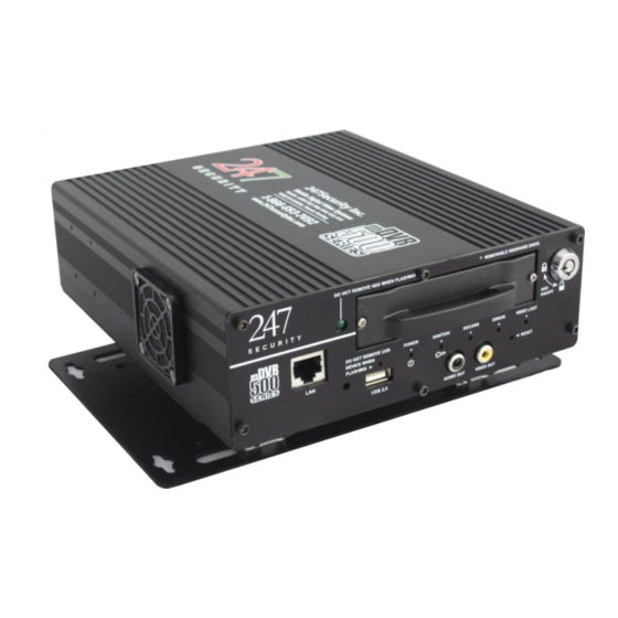
1. mDVR514M system (L – no WIFI or W – w/WIFI)
2. One to Four Cameras, depending on your order
3. One Camera Cable per Camera
4. Power cable
5. Digital I/O cable
6. Event Marker
7. USB A-to-MiniB Cable
8. Ethernet Network Cable
9. RCA Adapter
Optional equipment:
1. GPS module
2. USB Flash Memory Drive for GPS data retrieval
3. USB Flash Memory Drive (Memory Stick) for Marked Event retrieval
4. Additional hard drives
The installation of your mDVR500 is comprised of the following five steps:
1. DVR and Camera Placement
2. Cables
3. Connections and On-site Preparations
4. Equipment Test
5. DVRViewer Application and Camera Aiming
1
Advertisement
Table of Contents

Related Manuals for 247Security mDVR 500 Series


Summary of Contents for 247Security mDVR 500 Series
- Page 1 514M Series Quick Guide - INSTALLATION Thank you for purchasing a 514M Series DVR from 247Security Inc. For any questions regarding the installation procedure, please contact 247Security Inc. Technical Support at 1-866-693-7492. Your order should contain the following components (per system): 1.
- Page 2 1. DVR AND CAMERA PLACEMENT The first step is to determine the most appropriate location for the DVR and cameras. Mounting locations will vary depending on the bus style, body manufacturer and bus year. Mounting orientation can be horizontal, vertical, or at angles for spatial consideration.
-
Page 3: Camera Cables
CAMERA CABLES Camera Cables (available in lengths of 15, 35 or 50 feet) use the STP (shielded twisted pair) cable standard. The Camera Cables are connected using molded 2x3 Molex interfaces that are keyed to prevent improper mating. Each connector uses a clip to snap securely to each camera and to the inputs on your DVR. Typical configurations are such that the passenger cameras connect to inputs 1 and 2;... - Page 4 GPS MODULE (OPTIONAL) The GPS Module is an external GPS receiver and is optional equipment. The module’s cable measures 15 feet long and uses an RP-SMA Jack interface to connect to the DVR. The module has a magnetic base; however, it is recommended that the module be secured to a surface through its screw holes.
- Page 5 SETTING UP YOUR LAPTOP FOR CONNECTING TO THE DVR At any point in the installation, the DVR can be connected to a laptop to provide the installer a live view of the cameras for aiming purposes. Using the included cross-over cable, attach one end to the LAN 1 port on the DVR, and the other end to the Ethernet LAN port on the laptop.
-
Page 6: Equipment Test
4. EQUIPMENT TEST When all of the cameras, cables, and add-on modules have been installed and when the DVR is connected to your on-site laptop, the completed setup needs to be tested. To begin the test, ensure the DVR’s Hard Drive is inserted in the DVR and the lock is turned to the locked position and then turn the vehicle’s ignition to ACC or ON. -
Page 7: Getting Started
5. DVRViewer APPLICATION AND CAMERA AIMING GETTING STARTED Insert the 247Security Inc. CD-ROM into your on-site laptop and install the DVRViewer application. Owners of our previous generation of digital surveillance systems (400Series DVR) will have our old DVR application installed, called DVR Client. - Page 8 DVRViewer MAIN WINDOW To connect to your DVR, click on Play to open the action menu and select Live View. DVRViewer will scan your computer’s network port for the connected DVR. When your DVR is detected, it will appear on the device list along with the IP address of which one of its two LAN ports you inserted the Crossover Cable.
- Page 9 The DVR will have been completely configured prior to shipment to the following parameters: Date and time adjusted to your local time zone One recording channel activated per camera ordered Recording parameters, including frame rate, quality, and resolution, configured to recommended settings ...
- Page 10 514M Series DVRs can use custom names of your choice to identify each vehicle in your fleet from one another. The system’s name can be changed on the System page of DVR Setup after any changes, make sure and select the APPLY button at the bottom of the screen and the CONTINUE button to accept the requested changes.
- Page 11 DVR’s internal software configuration and does not provide audio preview from the cameras’ microphones. Thank you for choosing 247Security Inc. For any questions regarding the installation procedure, please contact 247Security Inc. 1-866-693-7492. Technical Support at...
Need help?
Do you have a question about the mDVR 500 Series and is the answer not in the manual?
Questions and answers