
Related Manuals for 247Security mDVR514M


Summary of Contents for 247Security mDVR514M
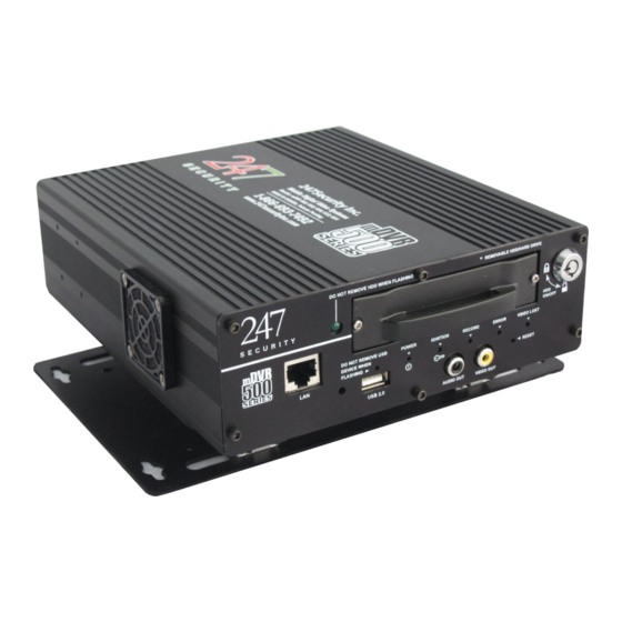
- Page 1 USER MANUAL mDVR514M Rugged Digital Video Recorder for In-Vehicle Applications 4 Video/Audio Channels 30 fps per Channel V11.0308...
-
Page 2: Table Of Contents
TABLE of CONTENTS 1. GENERAL INFORMATION AND SPECIFICATIONS 1.1. INTRODUCTION 1.2. SPECIFICATIONS 1.3. DIMENSION 1.4. CONNECTORS & LED LOCATIONS 1.4.1. FRONT PANEL 1.4.2. BACK PANEL 2. PREPARATION FOR USE 2.1. FRONT CONNECTORS 2.1.1. 10/100 BASE-T LAN CONNECTOR 2.1.2. VIDEO OUT CONNECTOR 2.1.3. - Page 3 3.1.6. USB ACTIVITY LED 3.2. HDD ON/OFF LOCK 3.3. MEDIA STORAGE REMOVAL 3.4. WIRELESS VIDEO RETRIEVAL 3.5. REMOTE POWER CONTROL 3.6. EVENT MARKING AND RETRIEVAL 4. CONNECTING TO DVR 4.1. IP CONFIGURATION 4.2. CONNECT CROSS-OVER CABLE 4.3. SETTING UP YOUR PC 4.3.1.
- Page 4 5.6.4. RESOLUTION 5.6.5. FRAME RATE 5.6.6. BIT RATE MODE 5.6.7. BIT RATE 5.6.8. PICTURE QUALITY 5.6.9. BRIGHTNESS, CONTRAST, HUE, AND SATURATION 5.6.10. TRIGGERS 5.6.11. PRE-RECORDING & POST-RECORDING TIME 5.6.12. SHOW GPS SPEED ON OSD & SPEED DISPLAY 5.6.13. SHOW GPS COORDINATE ON OSD 5.6.14.
-
Page 5: General Information And Specifications
The compression algorithm mainly runs on a DSP Engine, therefore freeing up valuable resources within the system to do other jobs. The mDVR514M... - Page 6 USB. 2.0 Integrated heater Wireless Network WLAN 802.11g/n GPS module can be connected to DVR using one cable, up to 40’ in length GPS data can be logged for over 15 years Ethernet 10/100 Base-T Ethernet port ...
- Page 7 Input Power Range +8 VDC ~ +24 VDC normal operating voltage +6 VDC ~ +28 VDC abnormal operating voltage up to 10 seconds Over and under voltage protection Ignition Signal / Power Down Timer Software configurable delay power off signal from 1-120 minutes 50mA current draw in sleep mode after power down Power consumption Typical 12W (5C ~ 55C)
-
Page 8: Dimension
1.3. DIMENSIONS The dimensions used in the following 2 diagrams are in inches. -
Page 9: Connectors & Led Locations
1.4. CONNECTORS & LED LOCATIONS 1.4.1. FRONT PANEL HDD Safe USB Activity Removal Power Record Error Video Lost HDD On / Off Ignition Key lock 10/100 Base-T USB 2.0 Audio Video Removable Hot-Swap Hard Drive 1.4.2. BACK PANEL C.D.C. Power General Communications +8 ~ +24V... -
Page 10: Preparation For Use
2. PREPARATION FOR USE 2.1. FRONT CONNECTORS 2.1.1. 10/100BASE-T LAN CONNECTOR The RJ45 port allows access to the DVR from your laptop / computer using the included cross over cable. This port is labeled as LAN and has a default static IP address of 192.168.1.100. Pin Number Signal Description... -
Page 11: Back Connectors
2.1.4. VIDEO OUT CONNECTOR Connector type: RCA Jack Pin Number Signal Description Pin out Inside Video Video Signal Outside Ground 2.2. BACK CONNECTORS 2.2.1. WIFI CONNECTOR Connector type: RP-SMA Jack Pin Number Signal Description Pin out RF Signal RF Ground 2.2.2. -
Page 12: Power Input Connector
The mDVR514M has a built-in Intelligent power switcher that can operate from +8V ~ +24V DC-IN. The ON/OFF signal connects to the vehicle’s ignition signal. The mDVR514M uses this signal to trigger the power shut- off delay and the timing circuitry. The mMVR514M will remain ON until the shut-off delay time has been reached. -
Page 13: General Purpose Input / Output Connector
Ground 2.2.6. USB 2.0 CONNECTOR Connector type: 4-pin friction-lock header Pin Number Signal Description Pin out Cable Power +5 V -Data Balanced Data Line - +Data Balanced Data Line + Cable Ground 2.2.7. GPS CONNECTOR Connector type: RP-SMA Jack Pin Number Signal Description Pin out... - Page 14 2.2.9. EVENT MARKER CONNECTOR This connector is used to plug in the included event marker cable. Pin Number Signal Description Pin out DI_0 +12V OUT Output DO_0 Output DO_1 Output DO_2 2.2.10. G-FORCE CONNECTOR This connector is used to plug in the included event marker cable. Pin Number Signal Description Pin out...
-
Page 15: Cable Requirements
2.3. CABLE REQUIREMENTS 2.3.1. POWER CABLE A 15 ft three wire power cable is included for connection between the DVR and your vehicle power and ignition signals. It is highly recommended that in-line fast blow fuses (7.5 - 10 amps) be installed on the two power input connections for safety pre-cautions. -
Page 16: Sensor / Alarm Cable
2.3.3. SENSOR / ALARM CABLE A 15 ft sensor / alarm cable is provided to connect the 4 digital inputs, 1 digital output and motion sensor signals to the GP I/O port of the DVR. Wire Color Signal Description Picture Connects to Digital Input 1 Brown Input DI_1... -
Page 17: Gps Module Cable
2.3.5. GPS MODULE CABLE A GPS module attached to a 25 ft cable connects to the back of the DVR using a DB9 connector Connector Signal Description Picture Connects to GPS RP-SMA Jack connector on DVR 2.3.6. NETWORK CROSS-OVER CABLE This cable connects a computer / laptop to the 10/100BASE-T LAN connector using the network standard RJ45 connector so that user can setup the DVR parameters as well as preview the video and audio from the video channels. -
Page 18: Camera Lenses, What View, What Lens
2.4. CAMERA LENSES, WHAT VIEW, WHAT LENS The chart below can be used as a guide when ordering and installing cameras in your vehicle. Lens Angle of View Best focus distance Viewable distance 2.9mm 120° 4 ft 10 ft 3.6mm 92°... -
Page 20: Operation
The HDD On/Off lock mechanism is employed to prevent unauthorized operators from removing the media storage and tampering with video data. Turn key to position “Close” to lock media storage or “Open” to unlock. The mDVR514M will NOT record video if the lock mechanism is in the “Open” position 3.3. MEDIA STORAGE REMOVAL The media storage is hot swappable and can be removed and inserted without turning the ignition off. -
Page 21: Wireless Video Retrieval
1. Turn key to the “Open” position The “HDD Safe Removal LED” should start flashing. This process is necessary so that the mDVR514M can properly close all video/audio files and safely turn HDD power off. 2. Wait until “HDD Safe Removal LED” stops flashing and stays off 3. -
Page 22: Connecting To Dvr
4. CONNECTING TO DVR 4.1. IP CONFIGURATION The DVR default IP address is 192.168.1.100. The DVR is set up with a STATIC IP address to allow for a direct connection with a cross-over cable. During installation the DVR can be connected to a laptop allowing the installer to preview the cameras for aiming purposes. -
Page 23: Using Windows 7
4.3.3. USING WINDOWS 7 4.3.3.1. Click on the Start button in the lower left corner 4.3.3.2. Select control panel 4.3.3.3. Select and open Network and Sharing center 4.3.3.4. Select Change adapter settings 4.3.3.5. Right click on Local Area Connection 4.3.3.6. Go to properties and left click 4.3.3.7. -
Page 24: Dvr Setup
5.1. STARTING DVRVIEWER Verify that the mDVR514M has successfully powered up by checking the Power and Ignition LEDs which should be on and solid. The HDD Power LED should also be on. You can start the viewer software by finding the DVRViewer folder listed in the program folder in the start menu. -
Page 25: Connecting To Dvr
Select the DVR you want to connect to so that it’s highlighted and then click on “Connect” button. 5.4. SETUP LOGIN In this section, we will discuss how to configure the mDVR514M to meet your requirements. The process is straightforward and easy to follow; the DVR setup is divided into six major components: SYSTEM, CAMERA, SENSOR, NETWORK, STATUS and TOOLS. -
Page 26: System Configuration Menu
5.5. SYSTEM CONFIGURATION MENU The system configuration menu is where you configure general parameters such as the name of the DVR, time zone, shutdown delay, etc. Also the G-Force set-up parameters are here if the Drive-Safe module is attached to the DVR. -
Page 27: Dvr Server Name
This feature is illustrated by clicking on “Play” and selecting “Live View”; you will see a list of all mDVR514M servers that you can select. By Clicking on any selected DVR server name you gain access to that particular mDVR514M system. -
Page 28: Shutdown Delay (S)
5.5.4. SHUTDOWN DELAY (S) The Shutdown Delay parameter is used to control how long you want to keep the mDVR514M recording after the ignition key is switched to the OFF position in the vehicle. For instance, once the ignition key is switched OFF, the system will delay another x seconds (x seconds is the number that you have entered in the box from 10 seconds to 1200 seconds (20 minutes)) before shutting off mDVR514M system’s power completely. -
Page 29: Minimum Available Disk Space (Mb)
Let’s say you entered 100MB into this box, the mDVR514M records until it detects that you only have another 100MB of available space on the recording media. The mDVR514M will intelligently perform a “ring – recording” which means the mDVR514M will delete old video files that it doesn’t need, to free up space for new video files. -
Page 30: Stop Recording When Play Back
5.5.10. STOP RECORDING WHEN PLAY BACK This option will disable recording when the DVRViewer application is connected to the mDVR in play back mode. Click this check box to enable this feature which will improve simultaneous multiple video channel play back. 5.5.11. -
Page 31: Enable Smart Upload
5.5.16. ENABLE SMART UPLOAD This needs to be enabled for automatic upload of Marked Video Events, Requested Video, GPS and Drive-Safe™ data via the WIFI Touchdown system. 5.5.17. ENABLE BUZZER If this option is enabled and you have an event marker button with the buzzer option, you will receive an audio tone when the DVR powers up and a camera signal is not working. -
Page 32: Camera Configuration Menus
5.6. CAMERA CONFIGURATION MENUS The mDVR514M series is available in 2, 4 and 8 camera inputs configurations. Each camera input can be configured individually to have different characteristics such as picture quality, frame rate, resolution, recording mode, etc… You can select any camera by clicking on its tab where a sub-menu is available for configuration. -
Page 33: Enable Camera
5.6.1. ENABLE CAMERA Click the check box to enable or disable the camera input. 5.6.2. CAMERA NAME Each camera can have a different name based on where it is located in the vehicle. The value can be up to 16 characters long. -
Page 34: Trigger By Motion
In this mode, the DVR only records if it detects an event trigger on one of the programmable sensors. If this is the mode you want your DVR to use then don’t forget to enable the required sensors. 5.6.3.3. TRIGGER BY MOTION The DVR recording can also be triggered by motion. -
Page 35: Bit Rate Mode
5.6.6. BIT RATE MODE VBR is the setting pre-set from the manufacturer and is the recommended encoder bit rate control mode. Using this setting will enable the video to be recorded using maximum compression but maintaining picture quality. 5.6.7. BIT RATE The bit rate is also pre-set from the manufacturer to the default setting of 1 Mbps. -
Page 36: Brightness, Contrast, Hue And Saturation
The picture quality is also pre-set from the manufacturer to the default setting of “high”. Changing this setting will increase or decrease the picture quality, the smaller the picture quality the smaller the file size but less picture quality; the higher the picture quality the bigger the file size and better picture quality. 5.6.9. -
Page 37: Show Gps Coordinate On Osd
GPS information is also available on the mDVR514M provided you have the GPS option which includes a GPS antenna that connects to the mDVR514M and is installed on the vehicle. GPS data is recorded on the storage media as well as embedded into the video stream. Place a check mark in the box to display and record the vehicle GPS speed in the video stream. -
Page 38: Recording, Video Lost & Motion Alarm
5.6.14. RECORDING, VIDEO LOST & MOTION ALARM The mDVR514M has four digital outputs that can be used to configure alarms. You can assign any of these events (Recording, Video Lost and Motion) to a specific output by changing the output number. For example, recording status is sent to Digital Output 1, Video Lost status is sent to Digital Output 2 etc…... -
Page 39: Sensor Number
5.7.1. SENSOR NUMBER Click on the drop down menu to select how many sensors are available in your unit. The mDVR514M is equipped with 6 sensors standard unless additional sensors are required for your application. -
Page 40: Network Menu
5.8. NETWORK MENU The default Ethernet IP address of the mDVR514M is “192.168.1.100” and should not be modified unless necessary. If this IP address is modified the user will NOT be able to access the DVR if the IP address is lost. -
Page 41: Tools Menu
This tab displays the current system configuration and a real time heath status summary of the DVR. Starting from the top, this tab informs the user which firmware versions are currently loaded, number of cameras, sensors and alarms the DVR currently supports and the current DVR time as well as your local computer time. The local computer time is extracted from your computer which is currently connected to the DVR. -
Page 42: Download Configuration
5.10.1. DOWNLOAD CONFIGURATION This option is useful and will save you time when multiple mDVR514M systems need to be configured. Once the DVR has been configured, click the “Download” button to save your settings to a file on your desktop or a location of your choice. -
Page 43: Upload Configuration
For example, you can rename the file to incorporate the vehicle name and the date it was configured like the following: “BUS109-310709.cfg”. 5.10.2. UPLOAD CONFIGURATION This option allows you to select a backup configuration file and upload it to the DVR. This feature will overwrite all the current settings with the settings from the configuration file. -
Page 44: Update Firmware & Mcu Firmware
Click “Upload” to start the upload process Click “Apply” to apply the new settings or “Continue” to review your new settings before applying. Once you apply the new settings there, the previous settings will be lost. It is recommended to click “Continue” so that you can verify all the new settings. - Page 45 This feature will allow the user to update the firmware and MCU firmware of the mDVR514M system if needed. Firmware updates may contain new features and improvements, the update process should only be done by a qualified technician. If the update process is not done correctly, your DVR may fail to start properly and must be retuned to your dealer for repair.
-
Page 46: Dvrviewer
5. Reconfigure System a. After DVR boot up, both Ignition LED (amber) and Power LED (green) should be on solid. b. Launch Internet Explorer Type http://192.168.1.100/ to access DVR setup d. Update settings to the settings previously recorded on paper e. -
Page 47: Introduction
The DVRViewer application allows user to preview, playback and setup the mDVR514M which can be installed on multiple computers or laptops. A laptop is very useful when installing the mDVR514M in the vehicle so that installer can properly aim the cameras and setup the camera parameters as well as system configuration. - Page 48 The first screen that appears when you start the DVRViewer application will be the LOGIN screen. If this is the first time logging in the default username and password will be “admin” and “247SECURITYINC”. Both the Username and password are case sensitive. If you forget or lose your password please contact 247Security Inc Technical Support for help.
-
Page 49: Live View
6.6. LIVE VIEW The feature is mostly used when setting up the mDVR514M so that the installer can properly aim the cameras in the vehicle. Once the DVRViewer application is running, click on the play button and select “Live View”. -
Page 50: Selecting Screen Layout
Installer should now be viewing the real time video from the cameras connected. The above screenshot shows four video channels enabled with only one cameras connected, if the mDVR514M is not receiving video from the camera, the video channel will display a black screen with “Video Lost” in the OSD (On-Screen-Display). -
Page 51: Disconnect
To playback recorded video, the media storage must be removed from the mDVR514M unit and plugged into your laptop / computer using the Mini USB Cable that was included with the purchase of your mDVR514M. Connect the Mini USB connector to the media storage device and the USB connector to your laptop / computer and start DVRViewer application. -
Page 52: Search Video By Calendar And Timeline Bar
After selecting the media storage device, DVRViewer will scan the media for video / audio and categorize it by time and date using the calendar and a time bar at the bottom of the screen. The above screenshot is an example of what should now be displayed on your desktop. -
Page 53: Search Video By Event
The timeline bar is used to display the available video in the time mode selected above. The different colors on the bar represent the different types of video. See below for description of the colors used in the timeline bar: Yellow: Recorded video searchable by moving bar along the time line or using the playback controls below the timeline bar. -
Page 54: Export Video
Name Description Slow Slows down playback speed Jump Backward 20 Seconds Jumps backwards video playback 20 seconds Pause / Play Pauses or plays video playback Jump Forward 20 Seconds Jumps forward video playback 20 seconds Fast Accelerates playback speed One Frame Forward Advances one frame forward while in Pause mode Audio All Channels/Single Switches audio playback from all channels simultaneously or a single channel... -
Page 55: Play File
The new video file with “.DVR” extension is an encrypted file and can only be played by the DVRViewer application; this feature disables the ability of manipulating the video data so that it can be used in legal matters. 6.8. PLAY FILE This button will prompt user to open a video clip previously saved on their hard disk, CD, DVD, USB thumb drive, etc…... -
Page 56: Snapshot
USERS 6.10.1. USER MANAGEMENT From the main screen click on “Users” to access the mDVR514M user management interface. There are two types of users, “User” with limited rights or “Administrator“ with full access to the mDVR514M system. A standard user with limited rights can preview and copy recorded video files from storage media. -
Page 57: Add/Delete User
6.10.2. ADD/DELETE USER Click on “New User” button to create a new user. Enter a user name and password and select the user type to create the new user. Only Administrator users can add or delete users. The default Administrator user called “admin”... -
Page 58: Support Information
7. SUPPORT INFORMATION 247Security Inc. provides several methods for contacting Technical Support listed below. Visit our website at www.247securityinc.com and click on “Support” Email us your questions directly to support@247securityinc.com Calling our direct line Toll-Free at 1-866-693-7492... -
Page 59: Limited Warranty
Subject to the terms and conditions listed below, during the applicable warranty period, Seller will repair or replace, at its sole option, free of charge any defective products returned prepaid. In the event that you have a problem with any Seller product, please call 247Security Customer Service and request a RETURN MERCHANDISE AUTHORIZATION (RMA) NUMBER. - Page 60 Judicial District of York, Province of Ontario. © 2009 -247Security, Inc. All rights reserved. The information in this publication is accurate in all respects, at time of writing. 247Security, Inc.
Need help?
Do you have a question about the mDVR514M and is the answer not in the manual?
Questions and answers