Table of Contents
Advertisement
Available languages
Available languages
Quick Links
Advertisement
Table of Contents

Related Manuals for Marklin Digital 60948


Summary of Contents for Marklin Digital 60948
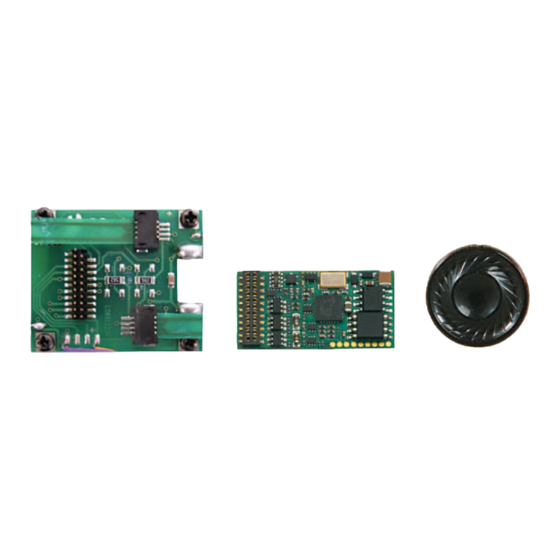
- Page 1 Nachrüstdecoder-Set Diesel-Lok 60948 Nachrüstdecoder-Set Elektro-Lok 60949 60948 Conversion Decoder Set for a Diesel Locomotive 60949 Conversion Decoder Set for an Electric Locomotive Nachrüstdecoder-Set...
-
Page 2: Table Of Contents
Inhaltsverzeichnis Seite Table of Contents Page Using the Product as Intended Bestimmungsgemäße Verwendung Lieferumfang Contents as Delivered Sicherheitshinweise Safety Notes Technical Informatio Technische Daten Funktionen Functions Decoder-Einbau Decoder Installation Multi-Protocol Operation Multiprotokollbetrieb - mfx-Protocol - mfx-Protokoll - fx-Protokoll - fx-Protocol - DCC-Protocol - DCC-Protokoll Physical Functions... -
Page 3: Bestimmungsgemäße Verwendung
Daten) betreiben. Diese Anleitung beschreibt den Einbau und die Einstellmög- Beim Umgang mit dem Lötkolben besteht die Gefahr lichkeiten der Decoder 60948 und 60949. Sofern nicht anders von Hautverbrennungen. erwähnt, beziehen sich die Funktionen auf beide Decoder. • Multiprotokollfähig (fx (MM), mfx, DCC und AC/DC). -
Page 4: Decoder-Einbau
Decoder-Einbau die jeweils diesem System zugeordnete Adresse verwen- det werden. Vor dem Einbau ist die Lokomotive auf einwandfreie mecha- • Anfahr- und Bremsverzögerung können getrennt vonei- nische und elektrische Funktion zu prüfen. Gegebenenfalls nander eingestellt werden. Kann über das Funktionsmap- muss die Lokomotive vor dem Umbau repariert werden. - Page 5 Die zwei Kardanwellen abziehen und für den Zusam- Motor von der Platine lösen. menbau zur Seite legen. Entsorgen der Platine, siehe Hinweis Seite 23. Die drei Kabel von der Platine ablöten. Beide Lötfahnen des Motors vorsichtig an der Platine auslöten. Warnung, Gefahr von Hautverbrennungen! Lötfahnen vorsichtig mit einer Pinzette aufbiegen.
- Page 6 Die zwei weißen Kabel durch den Lokrahmen führen. Die neue Platine auf den Motor legen, die Lötfahnen wieder vorsichtig zurückbiegen. Motor mit beiden Lötfahnen an die Die zwei Kardanwellen in die Aufnahmen stecken und neue Platine anlöten. zusammen montieren. W = weiß...
- Page 7 Beide weiße Kabel an den Lautsprecher anlöten. Platine festschrauben und Kabel anlöten. Den Haltebügel in die dafür vorgesehene Aufnahmen drücken. R = rot BR = braun...
-
Page 8: Multiprotokollbetrieb
Multiprotokollbetrieb Decoder einstecken, auf richtigen Einbau achten. Modell noch ohne Gehäuse auf dem Programmiergleis einer Prü- Analogbetrieb fung unterziehen. Wenn der Decoder einwandfrei arbeitet, kann das Gehäuse montiert werden. Der Decoder kann auch auf analogen Anlagen oder Gleisab- schnitten betrieben werden. Der Decoder erkennt die ana- loge Wechsel- oder Gleichspannung (AC/DC) automatisch und passt sich der analogen Gleisspannung an. -
Page 9: Mfx-Protokoll
Hinweis: Beachten Sie, dass nicht alle Funktionen in allen wieder hergestellt werden. Digital-Protokollen möglich sind. Unter mfx und DCC können • Funktionsmapping: Funktionen können mit Hilfe der einige Einstellungen von Funktionen, welche im Analog- Central Station 60212 (eingeschränkt) und mit der Central Betrieb wirksam sein sollen, vorgenommen werden. -
Page 10: Dcc-Protokoll
in Abhängigkeit der Folgeadressen nutzbar. der CV-Tabelle gekennzeichneten CV möglich. Die Pro- grammierung auf dem Hauptgleis (PoM) muss von Ihrer • Alle Einstellungen aus dem Funktionsmapping der mfx- Zentrale unterstützt werden (siehe Bedienungsanleitung oder DCC-Programmierung werden für fx (MM) übernom- ihres Gerätes). -
Page 11: Physikalische Funktionen
Physikalische Funktionen Bahnhofsansage Die Lok fährt erst nach beendeter Ansage an. Jede dieser Funktionen muss extern an die Platine ange- schlossen werden. Man spricht daher von physikalischen Türen öffnen/Türen schließen Funktionen. Jedem physikalischem Ausgang (AUX / Licht) Solange die Funktion Türen öffnen/Türen schließen aktiv ist, kann im Digitalbetrieb ein eigener Modus/Effekt zugeordnet fährt die Lok nicht an. -
Page 12: Schaltbare Funktionen
f0 f8 Schaltbare Funktionen systems STOP mobile station Digital/Systems Spitzensignal function/off Funktion f0 Funktion f0 Geräusch: Puffer an Puffer Funktion 1 Funktion 8* Funktion f1 Funktion f1 Geräusch: Betriebsgeräusch Funktion 2 Funktion 2* Funktion f2 Funktion f2 Geräusch: Horn 1 Funktion 3 Funktion 6* Funktion f3... -
Page 13: Lautstärke Ändern
Lautstärke ändern mfx-Protokoll: Die Gesamtlautstärke der Geräuschfunktionen lässt sich mit der Central Station 60213/60214/60215 komfor- tabel im CV Menü Sound ändern. Das Funktionsmapping (zuordnen der Funktionstasten) und die individuelle Lautstärke- Einstellungen erfolgt über die Funktionstasten. Die Sound-Nummer wird für das Funktionsmapping benötigt. fx-Protokoll: Im fx-Protokoll kann nur die gesamte Lautstärke mit CV 63 geändert werden. -
Page 14: Cv-Tabelle Fx (Mm)
Default Bedeutung Bemerkung 60949=24 Adresse ist immer aktiv und ist nicht abhän- Adresse 1 (Hauptadresse) 1-255 (1 - 80)* 60948=72 gig von CV 49. 60949=1 Geschwindigkeit bei kleinster Fahrstufe 1-255 (1 - 80)* Minimalgeschwindigkeit (Vmin) 60948=5 Wert muß kleiner sein als Vmax, CV 5. - Page 15 CV-Tabelle fx (MM) Werte Default Bedeutung Bemerkung Konfiguration: Das Richtungsverhalten bezieht sich auf die Bit 0 : Richtungsverhalten der Lok umkehren Fahrtrichtung und auf das Licht. 0 = Richtung normal, 1 = Richtung umkehren Die Anzahl der Fahrstufen und Halbstufen Bit 1 : Anzahl der Fahrstufen, 0 - 7 sind vom Fahrgerät abhängig.
- Page 16 ... 1 : ohne Analog geregelt 1 - 255 (0 - 63)* 60949=160 Motorregelung - Regelreferenz Absolutes Vmax für Motorkennlinie {x4} 60948=195 1 - 255 (0 - 63)* Motorregelung - Regelparameter K Regelanteil P {x4} 1 - 255 (0 - 63)*...
- Page 17 Bit 0 : Fahrtrichtung speichern 60949=25 Adresse kann de/aktiviert werden, 1 - 80 Adresse 2 (1. Folgeadresse) 60948=73 in Abhängigkeit von CV 49. Hinweis für die CS1: (140) 1 - 63 {x4} Analog DC Anfahrspannung Die CS1 zeigt den Wert invertiert an.
-
Page 18: Cv-Tabelle Dcc
(siehe CV 67) 60948=5 CV-Wert multipliziert mit 0,9 ergibt die 60949=18 Anfahrverzögerung (AV) 0 - 255 Zeit vom Stillstand bis Maximalgeschwin- 60948 =32 digkeit. CV-Wert multipliziert mit 0,9 ergibt die 60949=15 Bremsverzögerung (BV) 0 - 255 Zeit von Maximalgeschwindigkeit bis 60948=17 Stillstand. - Page 19 CV-Tabelle DCC Bedeutung Werte Default Bemerkung 1 - 127 = Traktionsadresse 0 = keine Traktion Traktionsadresse 0 - 255 +128, Bit 7 = Richtung umpolen bei Traktion 0 = Fkt. # nur für Lokadresse Funktionen F1 - F8 bei Traktion 0 - 255 1 = Fkt.
- Page 20 ... 0 : mit Analog geregelt ... 1 : ohne Analog geregelt 60949=160 Motorregelung - Regelreferenz 0 - 255 Absolutes Vmax für Motorkennlinie 60948=195 Motorregelung - Regelparameter K 0 - 255 Regelanteil P Motorregelung - Regelparameter I 0 - 255 Regelanteil I 0 = ungeregelte PWM für Sinus...
- Page 21 CV-Tabelle DCC Bedeutung Werte Default Bemerkung Das Quietschen beginnt, je größer der Wert ist um so früher, je kleiner der Wert Bremsenquietschen Schwelle 0 - 255 ist um so später. Ist der Wert zu klein, wird kein Quietschen ausgelöst. CV-Wert dividiert durch 128 ergibt Vorwärts Trimm 0 - 255 den Faktor, mit dem die Fahrstufe bei...
- Page 22 Vmin Analog DC 0 - 255 muss kleiner CV 177 sein 60949=215 Vmax Analog DC 0 - 255 muss größer CV 176 sein 60948=230 Vmin Analog AC 0 - 255 muss kleiner CV 179 sein 60949=215 Vmax Analog AC 0 - 255 muss größer CV 178 sein...
-
Page 23: Störungen Beheben
Störungen beheben Entsorgung Bei Betrieb mit verschiedenen Protokollen kann es zu Hinweise zum Umweltschutz: Produkte, gegenseitigen Störungen kommen. – Es wird empfohlen, die die mit dem durchgestrichenen Mülleimer Anzahl der Protokolle zu reduzieren. Nicht benötigte Proto- gekennzeichnet sind, dürfen am Ende ihrer kolle im Lokdecoder und falls möglich auch in der Zentrale Lebensdauer nicht über den normalen Haus- deaktivieren. -
Page 24: Meine Persönlichen Decoder-Einstellungen
Meine persönlichen Decoder-Einstellungen Lokomotive: Adresse CV - CV - CV - CV - CV - CV - CV - CV - CV - CV - CV - CV - CV - CV - CV - CV - CV - CV - CV -... -
Page 26: Using The Product As Intended
These instructions describe the installation and the possible • Operate the decoder only with the authorized voltage settings for the 60948 and 60949 decoders. Unless otherwise (see technical data). stated, the functions refer to both decoders. There is a danger of burning yourself when working •... -
Page 27: Decoder Installation
• Acceleration and braking delay can be set separately Decoder Installation from each other. Any function button desired can be as- The locomotive must be checked before installing the de- signed using the function mapping. coder to make sure that it (locomotive) is in good mechanical •... - Page 28 Loosen the motor from the circuit board. Remove the two cardan shafts and place them off to the side for reassembling the locomotive later. Dispose of the circuit board; see note on page 46. Unsolder the three wires from the circuit board. Carefully unsolder the two solder tabs for the motor from the circuit board.
- Page 29 Guide the two white wires through the locomotive frame. Lay the new circuit board on the motor, and carefully bend the solder tabs back into place. Solder the motor with Stick the two cardan shafts into their sockets and reas- both solder tabs to the new circuit board.
- Page 30 Solder both white wires to the speaker. Screw the circuit board into place and solder the wires to it. Press the mounting bracket into the socket provided for it. R = red BR = brown...
-
Page 31: Multi-Protocol Operation
Multi-Protocol Operation Plug the decoder into the circuit board and make sure you have plugged it in correctly. Place the model, with the body Analog Operation left off, on the programming track and test it. If the decoder This decoder can also be operated on analog layouts or works with no problems, the body can be put on the locomo- areas of track that are analog. -
Page 32: Mfx-Protocol
Note: Please note that not all functions are possible in all • The default settings (factory settings) can be produced digital protocols. Several settings for functions, which are repeatedly. supposed to be active in analog operation, can be done • Function mapping: Functions can be assigned to any of under mfx and DCC. -
Page 33: Dcc-Protocol
• The first four functions and the lights can always be con- • The CVs can be programmed in any order desired. (Pro- trolled by means of the first address; additional functions gramming can be done on the main track PoM). The PoM can be used, depending on the consecutive addresses. -
Page 34: Physical Functions
Physical Functions Opening Doors / Closing Doors The locomotive does not start running as long as the func- Each of these functions must be connected externally to the tion “opening doors / closing doors” is active. The locomo- circuit board. We therefore speak of physical functions. A tive starts accelerating according to the ABV that has been unique mode/effect can be assigned to each physical output set/activated only when the function has been deactivated... -
Page 35: Controllable Functions
f0 f8 Controllable Functions systems STOP mobile station Digital/Systems Headlights function/off Function f0 Function f0 Sound effect: buffer to buffer Function 1 Function 8* Function f1 Function f1 Sound effect: operating sounds Function 2 Function 2* Function f2 Function f2 Sound effect: horn 1 Function 3 Function 6*... -
Page 36: Volume Settings
Volume settings mfx protocol: The total volume for the sound functions can be changed easily with the 60213/60214/60215 Central Station in the CV menu “Sound”. The function mapping (assigning the function buttons) and the individual volume settings are done with the function buttons. The sound number is required for the function mapping. fx protocol: In the fx protocol only the total volume can be changed with CV 63. -
Page 37: Cv Table For Fx (Mm)
Values Default Notes 60949=24 Address is always active and is not subject Address 1 (main address) 1-255 (1 - 80)* 60948=72 to CV 49. 60949=1 Speed at the smallest speed level. Value Minimum speed (Vmin) 1-255 (1 - 80)* 60948=5 must be smaller than Vmax, CV 5. - Page 38 CV Table for fx (MM) Explanation Values Default Notes Configuration: The direction properties refer to the direc- Bit 0: Reverse the locomotive’s direction properties tion of travel and the lights. 0 = normal direction 1 = invert direction The number of speed levels and half levels Bit 1: number of speed levels 0 - 7 depend on the locomotive controller.
- Page 39 1 - 255 (0 - 63)* 60949=160 Absolute Vmax for motor characte- Motor feedback control – feedback control reference {x4} 60948=195 ristic 1 - 255 (0 - 63)* Motor feedback control – feedback control parameter K Feedback control portion P...
- Page 40 Bit 0: storing direction of travel 60949=25 Address can be activated/deactivated Address 2 (1st consecutive address) 1 - 80 60948=73 subject to CV 49. Note for CS1: (140) Analog DC startup voltage 1 - 63 {x4} The CS1 shows this value inverted.
-
Page 41: Cv Table For Dcc
(see CV 67) 60949=18 CV value multiplied by 0.9 gives the time Acceleration delay (AV) 0 - 255 60948 =32 from being stopped to maximum speed. 60949=15 CV value multiplied by 0.9 gives the time Braking delay (BV) 0 - 255 60948=17 from maximum speed to being stopped. - Page 42 CV Table for DCC Explanation Values Default Notes 1 - 127 = multiple unit address 0 = no multiple unit Multiple unit address 0 - 255 +128, Bit 7 = reverse polarity for direction when using multiple unit 0 = func. # only for locomotive address Functions F1 - F8 when using multiple unit 0 - 255 1 = func.
- Page 43 60949=160 Motor feedback control – feedback control reference 0 - 255 Absolute Vmax for motor characteristic 60948=195 Motor feedback control – feedback control parameter K 0 - 255 Feedback control portion P Motor feedback control – feedback control parameter I...
- Page 44 CV Table for DCC Values Explanation Default Notes The higher the value the sooner the squealing begins, the lower the value the Brake squealing threshold 0 - 255 later the squealing begins. If the value is too low, no squealing is activated. The CV value divided by 128 gives the fac- Forward trim 0 - 255...
- Page 45 0 - 255 Must be smaller than CV 177 60949=215 Must be larger than CV 176 Vmax Analog DC 0 - 255 60948=230 Vmin Analog AC 0 - 255 Must be smaller than CV 179 60949=215 Vmax Analog AC 0 - 255...
-
Page 46: Troubleshooting Problems
Troubleshooting Disposing When operating with different protocols you may have Products marked with a trash container problems in each mode at the same time. – We recommend with a line through it may not be disposed of reducing the number of protocols. Deactivate protocols at the end of their useful life in the normal in the locomotive decoder that are not needed and also household trash. -
Page 47: My Personal Decoder Settings
My personal decoder settings Locomotive: Adress CV - CV - CV - CV - CV - CV - CV - CV - CV - CV - CV - CV - CV - CV - CV - CV - CV - CV - CV -... - Page 48 Due to different legal requirements regarding electro-magnetic compatibility, this item may be used in the USA only after separate certification for FCC compliance and an adjustment if necessary. Use in the USA without this certification is not permitted and absolves us of any liabili- ty.
Need help?
Do you have a question about the 60948 and is the answer not in the manual?
Questions and answers