Table of Contents
Advertisement
Quick Links
Advertisement
Table of Contents

Related Manuals for Ama Tech Tank Fan


Summary of Contents for Ama Tech Tank Fan
- Page 1 Installation Guide Tank Fan...
-
Page 2: Table Of Contents
Contents PRE-INSTALLATION CHECKLIST Important Safety Instruction: Please Read & Save These Instructions Specifications & Components Product Overview Dimensions Installation Instructions Operating Conditions Operating Instructions Operating Instructions (cont.) Maintenance Instructions Troubleshooting New Unit Warranty Repair Out of Warranty Repair... -
Page 3: Pre-Installation Checklist
• I am aware with the local safety regulations and features of the fan. • I am aware to check the troubleshooting if there is any problem during installation process. • I am aware to conctact AMA Tech if there is any failure during installation process. -
Page 4: Important Safety Instruction: Please Read & Save These Instructions
Important Safety Instruction: Please Read & Save These Instructions To reduce fire hazard, electric shock or personal injury, please observe the following points: 1. Before repairing or cleaning unit, please turn off the power to the control unit, and lock the repair cut-off device in order to prevent accidental power-on. - Page 5 by pulling it crudely. Please hold the power cord firmly and pull it gently from the power socket. 10. Do not use this unit in conditions where there is exposure to harmful chemicals, salt water, acid rain or other corrosive elements, excessive humidity, snow, sleet, and/or strong winds. 1.
- Page 6 10. Do not use unsafe wiring during operation. If wiring is damaged, please contact your dealer or manufacturer. Do not try to fix the issue by unauthorized technicians. 11. Do not lay wires underneath carpets or similar coverings. Do not pass wires under or in- between furniture or electrical appliances.
-
Page 7: Specifications & Components
Specifications & Components Fan specifications: Model Tank Fan Fan diameter (m) Max. speed (RPM) Load current (A) 2A/4A Single phase voltage (V) 220/110 Max. energy consumption (W) Wind Volume at Max Speed (m³/min) 1413 Noise level <65 No. of fan blades... -
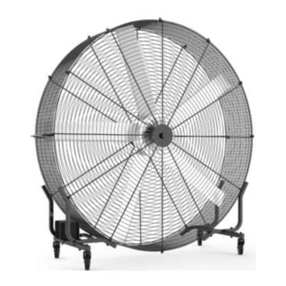
Page 8: Product Overview
Product Overview Kindly refer to below for the overview picture if you have successfully installed our product: Dimensions Side View Front View... -
Page 9: Installation Instructions
1. Insert base support bar (38x38cm), protect sharp edges with rectangular stopper. NOTE: TWO pieces of base support bars (38x38cm) are required for one tank fan. 2. Secure attachment between caster and base support bar. NOTE: Each caster requires ONE nyloc nut ½-13, and ONE hex bolt... - Page 10 3. Insert base support curved bar (30x30cm), protect sharp edges with rectangular stopper. NOTE: FOUR pieces of base support curved bars (30x30cm) are required for one tank fan. • Fan Assembly Please follow below steps to install the fan assembly: 1.
- Page 11 2. Find the center of spot-welded wire mesh and mark it accordingly. NOTE: TWO Pieces of wire mesh (330x40cm) are required for one tank fan. 3. #1 and #7 are the contact points (#1 is the TOP, #7 is the BOTTOM); #4 is the position for the galvanized handle washer;...
- Page 12 2. EIGHT sets of M10*30 screws are required to lock one side of the fan. 5. Find the contact point on the center of the spot-welded wire mesh, and reinforce with one more screw. NOTE: TWO screws (M6*20) are required for one tank fan.
- Page 13 6. Fasten screw(s) between base support and wire mesh. NOTE: EIGHT screws (M10*60) are required for one tank fan. 7. Fasten and secure screws on the 12 contact points between the side hooks and wire mesh. 8. Gently fasten but not tighten the screw and washer between the handle and...
- Page 14 10. Retrieve motor unit, and fasten the screw(s) with the electrical cable outlet facing down towards the base support. NOTE: 1. TWO screws (M30*60) are required for one tank fan; 2. The electrical cable outlet must face towards the bottom (i.e., base support).
- Page 15 11. Place the opposing metal fan cover to determine a horizontal plane, and adhere brand sticker. 12. Match the metal fan covers with the correct axis and secure with screws. 13. Tuck wire mesh inside the side hooks and align opposing covers. NOTE: Align brand sticker parallel to the handle.
- Page 16 14. Fasten and secure screws between the TWELVE side hooks and wire mesh. 15. Fasten screw between caster bar and base support curved bar. 16. Secure and tighten screw with tool.
- Page 17 17. Lift the fan upright and tighten the screws on the axis on the front and rear. NOTE: Ensure that the axis is aligned when tightening the screw. 18. Tighten the washer on control unit to the base support. NOTE: The control unit is to be installed on the base support near the handle.
- Page 18 19. Place a washer underneath the control unit and secure it tightly. NOTE: The electrical cable outlet must face towards the bottom. • Operational Testing Please follow below steps when tank fan is ready to use: 1. Connect power supply to fan and turn it on. Check for anomalies.
- Page 19 2. Record video of operation and document the electric current while the fan is on. NOTE: At maximum 270 RPM, the electric current should be below 5.5 amps.
-
Page 20: Operating Conditions
Operating Conditions Our tank fan will be working on optimal condition within below conditions: Environment Conditions Installation Site Indoor 0~40°C (= 32~104°F) Environmental To increase product reliability, please refrain from using temperature this product where temperature fluctuation is high Humidity... -
Page 21: Operating Instructions
Operating Instructions Please read manual carefully before operating the unit. Clear all obstacles in the vicinity of the unit to ensure safe distances and efficient ventilation. 1. Disconnect all power before maintenance. All maintenance operations are to be conducted by authorized technicians only. 2. - Page 22 5. Please operate the unit on even surfaces to avoid tipping. 6. To secure the unit, engage brake on caster (see diagram 1). To stabilize unit, step on jack-up mount to balance uneven surfaces (see diagram 3). 7. Before plugging power cord into power socket, wait for the unit to come to a stop with brake engaged on caster.
-
Page 23: Operating Instructions (Cont.)
Operating Instructions (cont.) (I) Power button: Turns the unit ON/OFF 1. Ensure that there are no obstacles or potential hazards in the operating space. 2. Check mains electricity and unit specification are compatible. 3. Ensure that the fan speed dial is set on slow (speed dial pointing towards bottom left). -
Page 24: Maintenance Instructions
Maintenance Instructions WARNING:Disconnect all power supply before conducting maintenance. Do not remove the power cord by pulling it crudely. Please hold the power cord firmly and pull it gently from the power socket. CAUTION: If the unit is suspected to be defective, please turn OFF control unit and then disconnect power supplies. -
Page 25: Troubleshooting
Button may flash and show an error code. If so, please refer to Troubleshooting - Error codes. If your issue cannot find the solution for the problems that happened, kindly contact AMA Tech’s local dealer through email or phone-call sales1@amatg.com.tw +886-2- 2268-0565. -
Page 26: New Unit Warranty
New Unit Warranty AMA Tech will ensure to replace any defective part (s), component (s), unit (s) within 7~21 working days from the arrival date as per the freight forwarder's shipping details. The terms and conditions are as follow: 1.1 Return merchandise packaging A "Re-packaging fee"... -
Page 27: Repair
Fault Found (NFF) 1.2.2 Freight charge: The dealer/buyer is responsible for the freight charge of returning the unit to AMA Tech. -
Page 28: Out Of Warranty Repair
Out of Warranty Repair AMA Tech may still offer maintenance service even when the warranty period expires or that the damage is not covered by the warranty. In such cases, standard maintenance service and repair charges apply. 1.1 Repair charge An invoice will be issued in advance to the dealer/buyer should such service be required.
Need help?
Do you have a question about the Tank Fan and is the answer not in the manual?
Questions and answers