Table of Contents
Advertisement
Quick Links
Advertisement
Table of Contents

Related Manuals for Ama Tech Exhaust Fan 54”


Summary of Contents for Ama Tech Exhaust Fan 54”
- Page 1 Installation Guide – Exhaust Fan (54”)
-
Page 2: Table Of Contents
Contents Pre-Installation Checklist ....................2 Important Safety Instruction: Please Read & Save These Instructions ......3 Specifications & Components..................6 Product Overview ......................7 Dimensions ........................7 Assembly........................8 Installation Instructions ....................10 Operating Conditions ....................17 Operating Instructions ....................18 Operating Instructions (cont.) .................. -
Page 3: Pre-Installation Checklist
• I am aware with the local safety regulations and features of the fan. • I am aware to check the troubleshooting if there is any problem during installation process. • I am aware to conctact AMA Tech if there is any failure during installation process. -
Page 4: Important Safety Instruction: Please Read & Save These Instructions
Important Safety Instruction: Please Read & Save These Instructions To reduce fire hazard, electric shock or personal injury, please observe the following points: 1. Before repairing or cleaning unit, please turn off the power to the control unit, and lock the repair cut-off device in order to prevent accidental power-on. - Page 5 8. This unit to be used for safe and general ventilation purposes only. Do not use this unit to expel hazardous, explosive, or gaseous chemicals. 1. All installations and wire connections must be conducted by qualified personnel in accordance with national regulations and standards.
- Page 6 tool. Do not use the tools for any purpose other than those specified by the manufacturer. 9. Warranty of brushless large fan does not cover equipment damage caused by improper installation. 10. Do not use this unit in conditions where there is exposure to harmful chemicals, salt water, acid rain or other corrosive elements, excessive humidity, snow, sleet, and/or strong winds.
-
Page 7: Specifications & Components
Specifications & Components Fan specifications: Model Exhaust Fan 54” Dimension (mm) 1460X1460X580 Max. Speed (RPM) 550RPM Load Current (A) 3±0.8 Single Phase Voltage(V) 220(V) Wind Volume at Max. Speed (m3/min) No. of fan blades Weight (kg) Fan components: 1. Protective Cover: Protects fan and user; 2. -
Page 8: Product Overview
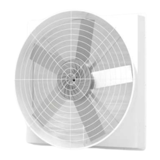
Product Overview Kindly refer to below for the overview picture if you have successfully installed our product: Dimensions Front View Side View... -
Page 9: Assembly
Assembly Please refer to below for the required components to install our product: Components Quantity Louver Rectangular support bar Exterior Shell NT3T15N0CN (Product number) Protective cover (wire mesh) Hex bolt (M10x1.25xL80) Washer (M10) Nyloc nut (M10x1.25) Nyloc nut (M12x1.25) Washer (M12) Spring washer (M12) Hex socket head cap screw (M12x1.25xL75) Self-tapping machine screw (M4xL 16) - Page 10 Connect to Power Connect to Motor...
-
Page 11: Installation Instructions
Installation Instructions After assembly, secure the fan unit with appropriate supports and fixtures. Please ensure that the installation is in accordance with local safety regulations. All electrical installation must be performed by a qualified electrician and comply with all local, state, and national regulations. - Page 12 3. Use an (M10*80) screw through a plain washer and a spring washer, and tighten it accordingly. • Motor Fantail Installation 1. Secure fantail at the end of the fan blade and tighten with M4 self-tapping machine screw. • Note: Tapped hole = TOP side, untapped hole = BOTTOM side. 2.
- Page 13 • Securing The Motor 1. Slide the motor’s shaft through rectangular support bar, and ensure to align performed hole. 2. Slide M12*75 screw through rectangular support bar’s preformed hole.
- Page 14 3. Use power tool to secure and tighten motor and support bar. • Front & Rear Protective Cover (Wire Mesh) & Louver Installation 1. Install protective cover(s) by tilting and reversing clasp on exterior casing of the exhaust fan.
- Page 15 2. Tighten protective cover and exterior casing with M4 self-tapping machine screw. 3. With the flat side of the louver facing up, and the uneven side facing down, embed the louver into exterior casing of the exhaust fan. 4. Ensure all four edges of louver are securely in place on the exterior casing. Tighten the four edges with M4 self-tapping machine screws.
- Page 16 • Caution 1. Of the four edges on the exterior casing, only one is flat. When positioned front and upright, the base of the exhaust fan should be flat (i.e., not curved). DOWN 2. When executing Step 3-1, ensure to pass wire from the motor through rectangular support bar.
- Page 17 3. When positioned front and upright, ensure that the air outlet/shutter on the louver points DOWNWARDS. This will safeguard the air outlet/shutter in the event of a malfunction.
-
Page 18: Operating Conditions
Operating Conditions Our tank fan will be working on optimal condition within below conditions: Environment Conditions Installation Indoor Site 0~40℃ (=32-104 F) Environmental To increase product reliability, please refrain from using this Temperature product where temperature fluctuation is high Humidity Below 90%RH Environment Avoid corrosive chemicals and/or flammable gas... -
Page 19: Operating Instructions
Operating Instructions Please read manual carefully before operating the unit. Clear all obstacles in the vicinity of the unit to ensure safe distances and efficient ventilation. 1. Disconnect all power before maintenance. All maintenance operations are to be conducted by authorized technicians only. 2. -
Page 20: Operating Instructions (Cont.)
Operating Instructions (cont.) ON/OFF Button Fan Speed Control (I) Power button: Turns the unit ON/OFF 1. Ensure that there are no obstacles or potential hazards in the operating space. 2. Check mains electricity and unit specification are compatible. 3. Ensure that the fan speed dial is set on slow (speed dial pointing towards bottom left). 4. -
Page 21: Maintenance Instructions
Maintenance Instructions CAUTION: Disconnect all power supply before conducting maintenance. WARNING: If the units is suspected to be defective, please turn OFF control unit and then disconnect power supplies. Contact your dealer or manufacturer promptly. WARNING: All maintenance operations are to be conducted by authorized technicians only. -
Page 22: Troubleshooting
Excessive loud noise Please record video (with audio) of incident and contact your dealer or manufacturer. If your issue cannot find the solution for the problems that happened, kindly contact AMA Tech’s local dealer through email or phone-call sales1@amatg.com.tw +886- 02-2268-0565. -
Page 23: New Unit Warranty
1.2.1 Units are deemed DOA if the defect(s) are not the result of improper operation, damage during freight transport, or, unauthorized repair. 1.2.2 AMA Tech has full authority to determine whether a defect is of natural causes, misuse, unauthorized modification or repair, or external forces (e.g., power interference, motor failure, improper installation, incorrect wire connection, etc.…) at our discretion. -
Page 24: Repair
Fault Found (NFF). 1.2.2 Freight Charger: The dealer/buyer is responsible for the freight charge of returning the unit to AMA Tech. -
Page 25: Out Of Warranty Repair
Out of Warranty Repair Ama Tech may still offer maintenance service even when the warranty period expires or that the damage is not covered by the warranty. In such cases, standard maintenance service and repair charges apply. 1.1 Repair Charge: An invoice will be issued in advance to the dealer/buyer should such service be required.
Need help?
Do you have a question about the Exhaust Fan 54” and is the answer not in the manual?
Questions and answers