
Related Manuals for Bertolini CHX Series


Summary of Contents for Bertolini CHX Series
- Page 1 PISTON PUMPS CHX Series Operation, maintenance and repair manual CHX Series Pumps Reggio Emilia - Italy Via F.lli Cervi 35/1 42124 REGGIO EMILIA - ITALY...
- Page 2 July 2018 Revised on: 1 June 2019 “BERTOLINI” thanks you for your preference. The product you have purchased is the result of the most modern technology and has been manufactured with materials able to ensure the best quality, durability and functionality.
-
Page 3: Table Of Contents
TABLE OF CONTENTS 1-GENERAL SAFETY REGULATIONS ....................5 2-DESCRIPTION OF THE PRODUCT ....................6 3-TECHNICAL FEATURES ........................7 3.1 Identification of components ........................8 3.2 Instructions for use ............................ 9 4-INSTALLATION ........................... 10 4.1 Pump connection to the frame ....................... 10 4.3 Pump-motor coupling .......................... - Page 4 The “Bertolini Technical Service” is at your disposal for any requirement as may arise when the product is used or serviced, or when relative accessories must be chosen.
-
Page 5: 1-General Safety Regulations
Strictly comply with the laws in force governing the disposal of substances that detach from the surfaces through the action of pressurized jets. Idromeccanica Bertolini declines all civil or criminal liability for damage or accidents to persons or things deriving from failure to comply with even only one of the aforementioned safety regulations. -
Page 6: 2-Description Of The Product
2-DESCRIPTION OF THE PRODUCT Bertolini high-pressure piston pumps are suitable for use with clean water at a maximum temperature of 60°C. Contact the “Bertolini Technical Service” if particularly corrosive additives and higher temperatures are used. The pump must be used in compliance with the specifications given on the data plate (fig. -
Page 7: 3-Technical Features
3-TECHNICAL FEATURES PUMP CHARACTERISTICS SERIES FLOW RATE PUMP POWER trans. to shaft at PISTONS MAX motor at max PRESSURE Shaft pressure MAX pressure and flow rate MODEL CODE l/min GPM bars Ø mm CHX 13-1000 74.1035.97.3 1000 14500 32.9 44.1 CHX 24-1000 74.1036.97.3 18.8 1000 14500... -
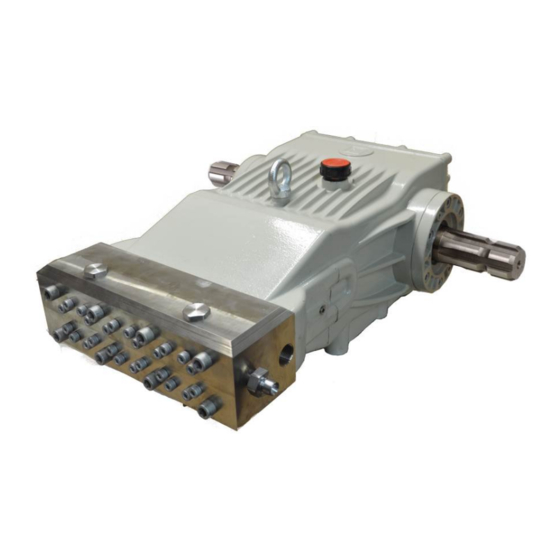
Page 8: Identification Of Components
3.1 Identification of components 1. Crankcase 7. Bearing supports 2. Oil fill plug with level dipstick 8. Pump shaft 3. Eyebolt for lifting 9. Identification plate 4. Head or pump body 10. Oil level plug 5. Delivery duct 11. Oil drain plug 6. -
Page 9: Instructions For Use
3.2 Instructions for use • The pump is exclusively designed for: – Use with clean water at temperatures between +4°C and +60°C for non-food purposes. – Use of detergents in a watery solution. • The pump cannot be used with: –... -
Page 10: 4-Installation
4-INSTALLATION Bertolini pumps comply with the safety regulations laid down by standard EN 809 and are designed to be coupled, either directly or via a transmission, to an electric, heat or hydraulic motor. The machine or system of which the pump is a part must be constructed in accordance with good engineering practice and with the safety regulations in force in the country in which the machine itself is installed. -
Page 11: V-Belt Transmission
4.4 Hydraulic connections The body of CHX series pumps features two 3/4” GAS inlets and four 1/2” GAS outlets, 2 of which can be used for a pressure gauge and safety valve. There is also a union for connecting the drainage outlet of the cooling circuit to a zero-pressure vessel or to the suction circuit, so as to re-circulate the fluid. -
Page 12: Filtering And Feeding Circuit
1-Feeder tank 2-Suction line 3-Drainage line 4-Pump IN-Suction union (there are two unions, but one can be used if preferred - on the side that facilitates the installation work) OUT-Delivery union (there are 4 unions available, to be used as required) D-Drainage union (there are two unions, but one can be used if preferred - on the side that facilitates the installation work) NOTE: If there is no tank in the application, connect the drainage line to the pump... -
Page 13: High Pressure Circuit
with a water head of at least 200 mm to prevent siphons from forming. – The suction area must be protected against turbulence created by the tank feeding pipe and return pipes, using closed diverters on the bottom. – The tank must be equipped with the safety devices indicated in sections 5.2 E and 5.2 F. -
Page 14: General Installation Layouts
4.7 General installation layouts TYPICAL CHX PUMP INSTALLATION 1) Level switch; 2) Thermostat; 3) Minimum tank capacity= pump flow rate x 4; 4) Closed diverters on bottom; 5) Feeding line clear passage Ø37 6) Filter on suction side (200 mesh 750 rpm; ≥200 mesh 1000 rpm); 7) Pressure switch / Pressure gauge to monitor supply;... - Page 15 4.8 Errors to avoid 1) Avoid, otherwise a “siphon” effect could be created; 2) Avoid 90° bends; 3) Avoid reductions in diameter; 4) Never connect the bypass line to the feeding line return.
-
Page 16: 5- Safety And Fault Prevention Devices
5- SAFETY AND FAULT PREVENTION DEVICES 5.1 Safety devices The system in which the pump is installed must always be equipped with the safety devices described below: Safety valve: this is an appropriately calibrated relief valve, which relieves the excess pressure if a fault occurs in the high-pressure circuit. - Page 17 tank to the pump, the higher will be the value of the vacuum created by the pump, a condition which consequently increases the risk of cavitation. This resistance is due to two crucial factors. Concentrated pressure losses: due to the presence, along the line, of bends, curves, unions, cocks, filters, etc., all obstructions to the regular flow of water which oppose a certain resistance, mainly depending on their size and geometric shape.
- Page 18 Table 2 Losses per 10 m (10 ft) of steel pipe for various Table 3 Loss of suction with dimensions and flow rates temperature of the water Table 4 Suction loss depending on height above sea level...
-
Page 19: D) Protection Against Overheating
CALCULATION EXAMPLE Example of a calculation for a CHX 21-1000 pump installed at 500 m above sea level Length of pipes (drawing) 1+1+2= 4.00 m 3.3+6.6+3.3= 13.20 ft Equivalent length 2X1.31= 2.62 m of unions (tab.2) 2X4.31= 8.62 ft Total length 6.62 m 21.82 ft H1 (tab.3) - Page 20 Otherwise, besides causing an unnecessary waste of energy, the water in the supply tank will overheat and contribute towards increasing the risk of cavitation. In addition, all the components in the circuit, especially the regulating valves, will be subjected to continuous and excessive stress.
-
Page 21: 6- Faq
6- FAQ Question: By how much must the pump speed rate be reduced to obtain a lower flow rate? Answer: Required speed rate = Required flow rate x Permissible max. rpm Permissible max flow rate Question: What motor pulley diameter is able to obtain this speed rate? Answer: Outer diam. -
Page 22: 7- Putting Into Service
7- PUTTING INTO SERVICE Preliminary inspections • Make sure that the feeding line is connected and hermetically sealed. • Make sure that the filter is clean. • Check that all the on-off valves (if any) along the feeding line are open and that water flows freely to the pump. -
Page 23: Start-Up
(operating pressure, distance of the nozzle from the object, etc.). Idromeccanica Bertolini S.p.A. declines all civil or criminal liability for damage to persons or things caused by improper use of the pump and the other parts of the system in which the pump is installed. -
Page 24: 8- Troubleshooting
8- TROUBLESHOOTING FAULTS CAUSES REMEDIES No water is being supplied Check the circuit and level of water in tank. When started, the pump fails to Valves blocked Check and replace if necessary. dispense water and produces no noise The delivery line is closed and prevents the Discharge the delivery line until water is dispensed air in the head from escaping regularly... -
Page 25: 9- Warranty
9- WARRANTY The liability of Idromeccanica Bertolini during the warranty period (12 months from the date of delivery) is limited to replacement of parts recognized as being defective by Idromeccanica Bertolini itself. The warranty is only valid when the defect can be ascertained by the Assistance Service and when it is not ascribable to improper use or negligent maintenance of the pump. -
Page 26: 10- Routine Maintenance
10- ROUTINE MAINTENANCE 10.1 Maintenance of drive mechanism and lubrication • Check the oil level at least once a week using the dipstick and top up if necessary. • Change the oil using SAE 80W - 90 oil once the pump has functioned for 50-100 hours after first start-up. -
Page 27: Hydraulic Circuit Maintenance
10.2 Hydraulic circuit maintenance Replacement of gaskets or valves are the only operations required. M8 screws for sleeve fastening Crankcase spacer M12 screws for Head head fastening 10.3 Disassembly of head and sleeves • Loosen the M8 screws that fasten the sleeves, without removing them. •... -
Page 28: Replacement Of The Suction And Delivery Valves
10.4 Replacement of the suction and delivery valves • Remove the M8 screws that fasten the sleeve and remove this latter, taking care to prevent the internal components from dropping. 10.4 A) Suction valves – Remove the plates, the springs and the spring guides from the sleeves (keep the components of the three pumping elements separate, if the used parts are going to be re-assembled). -
Page 29: B) Delivery Valves
10.4 B) Delivery valves • Remove the valve housings from the head. Certain models have a thread in the central hole of the valve housing. If this is the case, screw in an M8 bolt to facilitate the removal operations. In models without this thread, insert a plug and release the valve housings by applying lateral movements;... -
Page 30: Replacement Of High-Pressure Gaskets
10.5 Replacement of high-pressure gaskets • Remove the front glands from the sleeves. • Remove the high-pressure gaskets from the sleeves. • Position the thimble code 77.3941 on a sleeve and grease the tapering inner part. • Place a new front gasket in the thimble with the sealing lip pointing downwards. •... -
Page 31: Complete Re-Assembly Of The Suction-Delivery Valves
10.6 Complete re-assembly of the suction-delivery valves • Fit the valve components back into the sleeves in the following order: spring guide, spring, plate • Remove the axial gaskets (they may have remained in position or inside the head or on the valve housing during the disassembly operations). -
Page 32: Replacement Of Low-Pressure Gaskets
10.7 Replacement of low-pressure gaskets • Separate the crankcase spacer from the crankcase. Remove the rear glands from the crankcase spacer. Remove the rear pack (rear gasket and anti-extrusion ring). Replace the O-Rings of the outer slots of the rear glands. ... -
Page 33: Replacement Of Pistons
Grease the pistons Plug 10.8 Replacement of pistons • Separate the crankcase spacer from the crankcase. • Unscrew the pistons. • Thoroughly clean the remaining Loctite from the threaded holes of the piston guideways. • Apply Loctite 542 to the threads of the pistons and screw them into the piston guideways using 50 Nm torque. -
Page 34: Re-Assembly Of Head And Sleeves
• Grease the pistons, insert the anti-extrusion rings and rear gaskets. • Using plug code 77.3944, position the rear packs in the housings of the rear glands and seat them as far as they will go with the plug. Grease the pistons Plug 10.9 Re-assembly of head and sleeves Turn the shaft so as to expose the three pistons and grease. - Page 35 Position the pump crankcase assembly on the two screw-plugs 77.3943. Make sure • that the O-Rings on the crankcase spacer do not drop, then, with the aid of a plastic mallet, push the pump crankcase assembly fully against the crankcase spacer.
-
Page 36: Replacement Of Shaft Oil Retainers
10.10 Replacement of shaft oil retainers Disassembly: STEP 1: With the aid of a mallet, insert a flat-tip screwdriver into the metal support of the retaining ring (fig. 4). Fig. 4 STEP 2: Remove the retaining ring by levering as indicated in figure 5. -
Page 37: List Of Tools Required For Repairs
10.11 List of tools required for repairs The tools required for the repairs are available in a kit supplied on request. The individual tools can also be ordered individually: Complete kit Tool code Description Q.ty 77.3943 M12x270 assembly plug 77.3946 Plug for seating axial gasket of valves 77.9912.97.A 77.3944... -
Page 38: Manufacturer's Declaration
Directive 2006/42/EC, i.e. until the product to which this declaration refers forms a single entity with the final machine. Reggio Emilia 01.07.2018 Luigi Quaretti (Managing Director-Idromeccanica Bertolini S.p.A.)
Need help?
Do you have a question about the CHX Series and is the answer not in the manual?
Questions and answers