Advertisement
You have decided to show your preference for the "BERTOLINI" brand and have bought a
product which has been manufactured with the benefit of the most modern technology and
the finest materials, designed through research to ensure its improved quality, duration and
functionality.
We thank you for the trust shown in our products.
Please read this booklet with care and always keep it within easy reach. You will find it
useful in resolving any problem you may have with regard to the characteristics and
functionality of the product.
Thank you for having chosen "IDB - Bertolini"
This use and maintenance Manual is made up of the following chapters:
1.
General Rules.
2.
Product Description
3.
Technical Characteristics
4.
Choice of type of pump and the design of the plant
5.
Installation
6.
Use
7.
Ordinary Maintenance instructions
8.
Plant Construction Applications
9.
Special Safety Instructions
10. Guarantee
11. Problems and their Solutions
12. Instructions for a correct use of the Loader Valve
13. Resistance Table
14. Dimensions, Exploded Diagrams and Names
We at Idromeccanica Bertolini recommend that you read this Use and
Maintenance Manual carefully before installing and using the pump. You
should keep it within easy reach for any further reference.
should be considered as an integral part of the pump itself.
V. 2.0
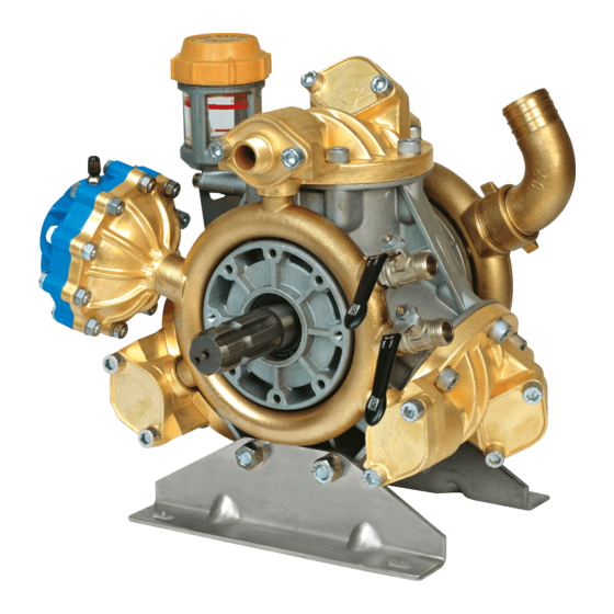
"IDB SERIES"
MEMBRANE PUMPS
- 1 -
The Manual
Advertisement
Table of Contents

Related Manuals for Bertolini IDB Series


Summary of Contents for Bertolini IDB Series
- Page 1 "IDB SERIES" MEMBRANE PUMPS You have decided to show your preference for the "BERTOLINI" brand and have bought a product which has been manufactured with the benefit of the most modern technology and the finest materials, designed through research to ensure its improved quality, duration and functionality.
-
Page 2: General Rules
IDROMECCANICA BERTOLINI has the right to up-date its products and their related manuals without being thereby obliged to up-date previous products and manuals, save in cases deriving exclusively from safety considerations. -
Page 3: Technical Characteristics
3. Technical Characteristics. When you receive delivery of the pump you should check that the plate affixed to it matches that illustrated below. The following details are displayed on the plate: 1. Pump model; 2. Maximum flow capacity (0 bars) in l/min. 3. - Page 4 IDB 1100 – IDB 1100S – IDB 1250 (Three membranes) IDB 1400 – IDB 1600 – IDB 1800 – IDB 2000 (Five membranes) 9) IDB1100s – IDB 1400/1600/1800/2000 (if present) 9) IDB1100/1250 – IDB 1400/1600/1800/2000 (if present) - 4 - V.
- Page 5 EN 6024.1, to avoid risks deriving from the use of electricity (cf. relevant part dealing with installation). Bertolini "IDB" membrane pumps are designed from materials which are compatible for use with water and the majority of pesticide and weed-killing products currently on sale in the market in the concentrations advised by the manufacturers(Cf.
-
Page 6: Installation
5. Installation The pump should be installed in perfect alignment with the mechanical transmission parts (pulleys, multipliers, reducers) and in a vertical position. This is necessary to ensure that the oil tank remains perpendicular to the ground. Check that the anchoring of the pump support to the machine base or installation location is appropriate and effected by means of properly locked screws in order to guarantee radial blocking. - Page 7 Particular attention should be given to the size of the Suction filter and/or of any diversion valve (three way valve). The flow capacity of the filter should be 1.5 times the flow capacity of the pump. An under-sized filter will reduce both the life of the membranes and the performance of the pump.
- Page 8 IDB PUMP OIL LEVEL EXAMPLE OF CALIBRATION OF ACCUMULATOR Accumulator: The pressure accumulator on the pump (if fitted) or on the delivery side (pressure side) is automatically pre-loaded at a pressure of 6 – 8 bars usable for the pump's maximum working pressure. For any different working pressure the accumulator pressure must be re-calibrated as indicated in the following table.
- Page 9 WORKING PRESSURE (bars) ACCUMULATOR PRESSURE (bar) 20 ~ 50 6 ÷ 8 10 ~ 20 5 ÷ 6 5 ~ 10 2 ÷ 5 (1 bar = 14,5 P.S.I.) For pressures less than 15 bars it is advisable to check that the accumulator pressure is at least equal to 1/3 of the working pressure to ensure a better control of the pulsing effect.
- Page 10 6.4. After use – It is essential, in order to avoid damage to the pump, to wash it after use. This should be done by running the pump under pressure for a few minutes with clean water. You should then empty it by reducing the pressure to "0" and leaving it to run dry for a few minutes.
- Page 11 7. ORDINARY MAINTENANCE INSTRUCTIONS WARNING! Before beginning any maintenance works or inspection of the pump, wash it with pure water, stop the power take off and disconnect it. Give particular attention to the stability and positioning of the machinery on which the pump is mounted to avoid inconvenience or nuisance to yourself or others.
- Page 12 M10 x 1.5= 44Nm (valve cover screws) 7.2) Replacement of Membrane/piston WARNING! If it is not possible to replace the membranes in the event of breakage, empty the water out of the carter and introduce oil or diesel in order to preserve the internal pump organs from oxidisation (rust).
-
Page 13: Oil Change
The membrane must be fitted with the piston at its lower rest position and with its edges perfectly inserted in the groove running round the circumference; e) Re-assemble the heads and lock the related screws; f) Fill the pump with oil (use only SAE 30 motor oil) through the tank while at the same time turning the shaft manually. - Page 14 WARNING! It is absolutely essential that the oil should not be disposed of into the drainage or sewage system or into the soil. 7.4) Maintenance Programme Maintenance intervals * Operation Every day Every 7 day Every year Check of oil level and condition Check accumulator pressure Check of plant (hoses and connections) Check and clean filters...
- Page 15 WARNING! Information relating to personal safety. READ THIS WITH CARE! The choice of the motor cardan shaft protective safety cones on Bertolini pumps is dependant on two fundamental factors: A) In accordance with “CE” safety regulations the overlapping between the pump safety cone and that of the cardan shaft must be “S”...
- Page 16 IDENTIFICATION OF "A" QUOTA. To obtain the "B" quota value it is necessary to refer to the manufacturer's catalogue specific to the cardan shaft used. The choice of the most appropriate safety cone must be effected on the basis that "S" (overlap) = A ÷...
- Page 17 Pulley motor pitch diameter: Pulley pump Pitch diameter: ø pp = ø p pulley motor x K N.B. for any special installation or use refer to Bertolini's "Technical Assistance Service" to avoid annoying difficulties. WARNING! All electrical connections must be carried out by specialised technicians.
-
Page 18: Special Safety Instructions
9. SPECIAL SAFETY INSTRUCTIONS – Do not work in the area where the pump is running without being protected by suitable clothing and goggles; – Do not work on the pump without disconnecting the power take off (stop the pump); –... - Page 19 42100 Reggio Emilia T IS ONLY AT THIS POINT THAT OUR GUARANTEE WILL BECOME OPERATIVE Idromeccanica Bertolini S.p.A. undertakes, within the period of twelve months from the date on which the pump is delivered, to provide replacement parts for any part which proves to be of defective manufacture.
-
Page 20: Problems And Solutions
11. Problems and Solutions Problem Causes Solution – One or more valves have worn – Check valves housings – Suction hose with air pockets – Check hose The pump does not or irregular bends achieve the desired – Worn nozzles or of incorrect –... - Page 21 INSTRUCTIONS FOR THE CORRECT USE OF THE LOADER VALVE DUPLO SPRAY VRP 83 KEY: 1. Regulator knob 2. Pressure release lever 3. Discharge connection (by-pass); 4. Use function taps a) Before starting up turn the lever anti-clockwise (or push it up) to the discharge position (by-pass).
-
Page 22: Resistance Table
Membranes made from ® , Viton and Desmopan are available on request, offering better chemical characteristics. N.B. FOR ANY SPECIAL INSTALLATION OR USE PLEASE CONTACT BERTOLINI'S "TECHNICAL ASSISTANCE SERVICE" TO AVOID ANNOYING PROBLEMS. - 22 - V. 2.0... - Page 23 CHEMICAL COMPATIBILITY TABLE Chemical Agent Viton Buna N (Nitrile ) Acetaldehyde Acetamide Acetate Solv. Acetic Acid, Glacial Acetic Acid 20% Acetic Acid 80% Acetic Acid Acetic Anhydride Acetone Acetylene Acryionitrile Alcohols Amyl Benzyl Butyl Diacelone Ethyl Hezyl Isobutyl Isopropyl Methyl Octyl Propyl A = No effect = good...
- Page 24 To be completed by the end customer. Set out details of the owner Surname First name Address: Post code : Locality: Country: Pump factory number (identifiable from plate) no. The pump has been bought from (indicate the dealer or machine manufacturer): Company: Address: Town:...
Need help?
Do you have a question about the IDB Series and is the answer not in the manual?
Questions and answers