Table of Contents
Advertisement
Available languages
Available languages
Quick Links
Advertisement
Table of Contents

Related Manuals for Bertolini C300 Series


Summary of Contents for Bertolini C300 Series
- Page 1 POMPE A PISTONI Serie C 300 Libretto istruzioni uso, installazione, manutenzione e norme di sicurezza Pompe Serie CK 3003 CA 316 C 3006 Reggio Emilia - Italy Via F.lli Cervi 35/1 42100 REGGIO EMILIA - ITALIA...
- Page 2 Giugno 2005 Revisione: Dicembre 2013 Lei ha accordato la sua preferenza a “BERTOLINI” ed ha acquistato un prodotto costruito con la tecnologia più moderna e materiali ricercati per la miglior qualità, durata e funzionali- tà. La ringraziamo per la fiducia riservataci.
- Page 3 Il “Servizio Tecnico Bertolini” è a disposizione per qualsiasi necessità che dovesse presentarsi al momento dell’uso e della manutenzione del prodotto, o per la scelta di ac- cessori ad esso collegati.
- Page 4 Osservare rigorosamente le disposizioni vigenti e relative allo smaltimento delle so- stanze che si staccano dalle superfici investite dal getto in pressione. L'Idromeccanica Bertolini declina ogni responsabilità civile o penale per danni od in- fortuni ad oggetti e persone che dovessero insorgere dalla inosservanza di una sola...
- Page 5 22- DESCRIZIONE DEL PRODOTTO Le pompe a pistoni ad alta pressione Bertolini sono indicate per l’uso con acqua pulita ad una temperatura massima di 60°C. Se utilizzati additivi particolarmente corrosivi e temperature più elevate è necessario di in- terpellare il “Servizio tecnico Bertolini”.
- Page 6 23- CARATTERISTICHE TECNICHE C 300 CARATTERISTICHE POMPE SERIES POMPA PORTATA POTENZA all'albero Albero Chiavetta PISTONI MAX Giri a pressione motore PRESSIONE a pressione e portata MAX diam dimens MODELLO CODICE l/min GPM N° Ø mm CK 1224 73.8500.97.3 1000 26,3 1160 15,7 21,0...
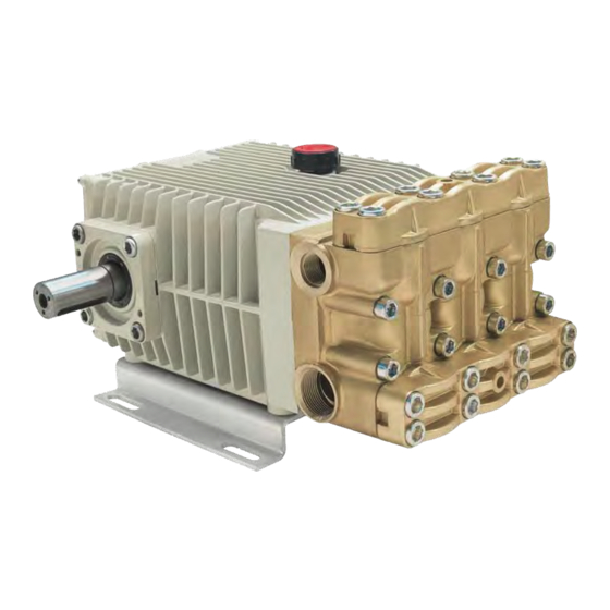
- Page 7 3.1. IDENTIFICAZIONE DEI COMPONENTI CK 3003-CA 316-CPQ 1. Targhetta di identificazione 2. Tappo carico olio con asta livello 3. Albero pompa 4. Condotto di man- data 5. Condotto di aspira- zione 6. Coperchio valvole aspirazione 7. Coperchio valvole mandata 8. Testata o corpo pompa 9.
- Page 8 3.2 DESTINAZIONE D’USO La pompa è esclusivamente destinata a: – Utilizzo con acqua pulita con temperatura compresa fra +4°C e +60°C per uso non alimentare. – Utilizzo di detergenti in soluzione acquosa. La pompa non può essere utilizzata con: –...
- Page 9 4- PRESCRIZIONI PER L’INSTALLAZIONE Le pompe Bertolini rispettano, in materia di sicurezza,la norma UNI EN 809 e sono destina- te ad essere accoppiate, direttamente o tramite un rinvio, con un motore elettrico, termico o idraulico. La macchina o l’impianto di cui fa parte la pompa deve essere costruita a “re- gola d’arte”...
- Page 10 Il gruppo pompa-motore deve essere adeguatamente fissato su un basamento sufficien- temente ampio e robusto. Tutte le connessioni elettriche devono essere realizzate da tecnici specializzati. Nel caso di accoppiamento diretto con il motore assicurarsi che: L’albero motore sia perfettamente in asse rispetto all’albero della pompa. La chiavetta di collegamento sia della lunghezza prescritta.
- Page 11 E’ consigliabile realizzare il tratto di tubazione immediatamente adiacente alla pompa con tubi flessibili idonei ad isolare il resto dell’impianto dalle vibrazioni prodotte dal gruppo pompa-motore Usare solo tubi rigidi o flessibili rinforzati antischiacciamento - Le tubazioni di alimentazione devono essere il più possibile rettilinee riducen- do al minimo curve, gomiti e brusche variazioni di sezione.
- Page 12 4.4 SCHEMI GENERALI DI INSTALLAZIONE TIPICA INSTALLAZIONE POMPE CK 3003-CA 316-CPQ TIPICA INSTALLAZIONE POMPE C 3006...
- Page 13 1) Livellostato; 11) Valvola di regolazione o 2) Termostato; depressurizzatrice; 3) Capacità minima cisterna: 12) By-pass valvola regolazione; portata pompaX4; 13) Mandata; 4) Paratie chiuse sul fondo; 14) Manometro; 5) Linea di aspirazione pompa 15) Accumulatore di pressione; passaggio minimo Ø47 per C3006 16) Linea di by-pass;...
- Page 14 5- DISPOSITIVI DI SICUREZZA E PREVENZIONE MALFUNZIONAMENTI 5.1 DISPOSITIVI DI SICUREZZA L’impianto che incorpora la pompa deve sempre essere sempre dotato dei dispositivi di sicurezza menzionati di seguito: Valvola di sicurezza: è una valvola di massima pressione, opportunamente tarata, che scarica la pressione in eccesso qualora dovesse manifestarsi un’anomalia nel circuito di alta pressione.
- Page 15 5.2 C) PROTEZIONE DALLE PULSAZIONI Un accumulatore caricato al 50-60% della pressione di utilizzo della pompa smorza le vi- brazioni che interessano tutto il sistema idraulico riducendo le sollecitazioni su tutto l’impianto. 5.2 D) PROTEZIONE DALLA CAVITAZIONE E DIMENSIONAMENTO DEL CIRCUITO DI ASPIRAZIONE (NPHSr) La cavitazione è...
- Page 16 DATI PER IL CALCOLO Tabella 1 Valori di NPHSr in base al numero di giri della pompa NPSHr (m) NPHSr (ft) 21,3 1450 22,3 1725 Tabella 2 Lunghezza equivalente dei raccordi, per varie dimensioni, in m (ft) di tubo d’acciaio Tabella 3 Perdite per 10m (10ft) di tubo d’acciaio per varie Tabella 4 Perdita di aspirazione con dimensioni e portate...
- Page 17 Tabella 5 Perdita di aspirazione in base all’altezza sul livello del mare ESEMPIO DI CALCOLO Esempio di calcolo per una pompa CK 1229 installata a 500 m sul livello del mare Lunghezza dei tubi (disegno) 1+1+2= 4,00 m 3,3+6,6+3,3= 13,20 ft Lunghezza equivalente 2X1,13= 2,26 m...
- Page 18 5.2 E) PROTEZIONE DAL SURRISCALDAMENTO Anche il funzionamento con acqua molto calda, oltre a ridurre la durata delle guarnizioni, è causa di fenomeni di cavitazione e deve essere evitato. Riduzione del regime di rotazione del motore. Se la pompa è collegata ad un motore elettrico comandato da un variatore di giri è conveniente installare un dispositivo che riduca il regime di rotazione del motore, e di conseguenza la portata della pompa, quando la valvola di bypass è...
- Page 19 6- FAQ Domanda: Di quanto si deve ridurre il numero di giri della pompa per avere una portata più bassa? Risposta: N. di giri richiesto = Portata desiderata x N.max di giri consentiti Portata max consentita Domanda: Che diametro deve avere la puleggia del motore per ottenere questo numero di giri? Risposta: Diam est.
- Page 20 7- MESSA IN SERVIZIO Controlli preliminari Verificare che la linea di alimentazione sia collegata e sia a tenuta ermetica. Verificare che il filtro sia pulito. Verificare che tutte le eventuali valvole di intercettazione presenti sulla linea di alimenta- zione siano aperte e che l’acqua arrivi liberamente alla pompa.
- Page 21 (pressione di utilizzo, distanza dell’ugello dall’oggetto ecc.). Idromeccanica Bertolini S.p.A. declina ogni responsabilità civile o penale, per danni a per- sone e cose, causati da uso improprio della pompa e delle altre parti presenti nell’impianto su cui la stessa è...
- Page 22 8- INCONVENIENTI E RIMEDI INCONVENIENTI CAUSE RIMEDI Manca acqua all’alimentazione Verificare il circuito ed il livello dell’acqua All’avviamento la pompa non eroga acqua e non produce nel serbatoio. nessun rumore Valvole bloccate Verificare ed eventualmente sostituire. La linea di mandata è chiusa e non per- Mettere in scarico la linea di mandata fino a mette all’aria presente nella testata di che l’acqua non esce regolarmente...
- Page 23 9- GARANZIA La responsabilità della Idromeccanica Bertolini nel periodo di garanzia (12 mesi dalla data di consegna) è limitata alla sostituzione delle parti che sono riconosciute difettose dalla Idromeccanica Bertolini.
- Page 24 Controllare almeno settimanalmente il livello dell’olio tramite l’apposita astina. Trascorse 50-100 ore di lavoro è necessario sostituire l’olio con olio SAE 75 W 90 arricchito dallo specifico additivo fornito da Idromeccanica Bertolini. Per quan- to riguarda la percentuale di additivo da impiegare fare riferimento alle istruzioni pre- senti sulla confezione.
- Page 25 10.2 Manutenzione delle valvole Smontaggio Le valvole sono facilmente accessibili dopo aver rimosso i due coperchi di ottone fissati cia- scuno da 8 viti M14 con esagono incassato 12mm 1. Togliere le valvole ed i relativi O-Rings. dalle sedi nella testata con l’aiuto di un picco- lo cacciavite.
- Page 26 10.3 Sostituzione guarnizioni di tenuta Smontaggio Lanterna 1. Con una chiave esagonale da Testata anteriore 10mm, svitare le viti di serrag- gio della testata, quindi rimuo- Lanterna vere la stessa dalla pompa Anello posteriore di spinta aiutandosi con un martello di plastica.
- Page 27 10.4 Sostituzione delle tenute olio pistoni Per effettuare agevolmente questa operazione occorre utilizzare un cacciavite con la punta affilata e sagomata come nella fig. 1. Fig.1 Ruotare l’albero della pompa fino a quando il pistone corrispondente all’anello di tenuta da smontare si trova al punto morto inferiore (fig.
- Page 28 10.5 Sostituzione delle tenute olio sull’albero Smontaggio: FASE 1: Con l’aiuto di un martello infilare un cacciavite a taglio piatto nell’armatura metallica dell’anello di tenuta (fig. 4). Fig. 4 FASE 2: Estrarre l’anello di tenuta facendo leva come indicato nella figura 5. Fig.
- Page 29 77.2331 D + 77.2331 A C 3006 Ø45 77.2331 C + 77.2331 A Tampone montaggio anello tenuta olio albero Tutte 77.2337 Tutte le attrezzature (es. estrattori, tamponi, ecc.) necessari per eseguire le operazioni sopra citate sono fornite da Idromeccanica Bertolini, su richiesta scritta.
- Page 30 11- DICHIARAZIONE DEL FABBRICANTE Dichiarazione del Fabbricante Direttiva Macchine 2006/42/CE (Allegato Il B) La Idromeccanica Bertolini S.p.A. dichiara sotto la propria responsabilità che la pompa della serie - CK 3003-CA 316-CPQ-C3006 con numero di serie (da riportare a cura dell'acquirente come riportato nella targhetta identificativa) - é...
- Page 33 PISTON PUMPS Series C300 Operating, Set –up, Service and Safety Instructions Manual CK 3003 CA 316 C 3006 pumps Reggio Emilia - Italy Via F.lli Cervi 35/1 42124 REGGIO EMILIA - ITALIA...
- Page 34 June 2005 Update: December 2013 You have decided to show your preference for “BERTOLINI” and have bought a product built with the most modern technology and the finest materials, famous for their quality, du- ration and functionality. We thank you for the trust shown in our products.
-
Page 35: Table Of Contents
The “Bertolini Customer Service” is available for any need arising when using or maintaining the product, and for choosing related accessories. c) No part of this handbook can be reproduced without the written permission of... -
Page 36: General Safety Regualtion
Strictly follow the current regulations related to the draining of substances taken down from the surfaces where the pressure jet is used. Idromeccanica Bertolini declines any civil or criminal liability for damage or acci- dents to persons or property arising from the failure to observe even only one of the... -
Page 37: Product Description
22- PRODUCT DESCRIPTION Bertolini high-pressure piston pumps are designed to be used with clean water, with a tem- perature of up 60°C. If you pump corrosive additives with higher temperature please consult the “Bertolini Tech- nical Service”. The pump operation must comply with the specifications indicated on the label (fig. 1); re- moving label implies the loss of any warranty. -
Page 38: Technical Specification
23- TECHNICAL CHART C 300 PUMP PERFORMANCE SERIES PUNPS FLOW RATE POWER REQUIRED Shaft PISTONS MAX RPM at max. PART pressure PRESSURE at max. pressure and flow Dia. Dimens. MODEL NUMBER l/min GPM N° Ø mm CK 1224 73.8500.97.3 1000 26,3 1160 15,7... -
Page 39: Identification Of Components
3.1. IDENTIFICATION OF COMPONENTS CK 3003-CA 316-CPQ 1. Identification label 2. Oil filling plug with dipstick 3. Pump shaft 4. Outlet 5. Inlet 6. Inlet valve cover 7. Outlet valve cover 8. Pump head 9. Crankcase 10. Mounting brackets 11. Bearing supports 12. -
Page 40: Aim Of Use
3.2 AIM OF USE The pump is exclusively devoted to: – Be used with clean water and temperature from +4°C up to +60°C, for not alimentary use. – Be used with detergents in watery solution. The pump cannot be used with: –... -
Page 41: Installation - Norms
4- INSTALLATION NORMS The Bertolini pumps, concerning security, comply with the rule UNI EN 809 and are des- tined to be coupled, directly or through a countershaft, with an electric motor, hydraulic mo- tor or gasoline engine. The machine or the system where the pump is located must be perfectly built observing the current safety rules in the country where the machine is in- stalled. -
Page 42: Inlet Circuit
In case of drive by a gearbox you have to follow the same previous recommendations of the coupling between engine/motor shaft – primary shaft and secondary shaft – pump shaft. In case of drive by pulleys check: – There is not any gap between shafts and pulleys. –... - Page 43 4.3 HIGH-PRESSURE CIRCUIT All the parts of the high-pressure circuit must have minimum performances (pressure and flow) at least 30% higher than the performances achievable by the pump. The high pressure circuit must be provided of a pressure regulating valve and a re- lief valve as indicated in the chapter 5.2 A and a pulsation dampener as indicated in the chapter 5.2 C The pressure relief valve and the regulating valve must have the label taking the...
-
Page 44: Typical Installation Scheme
4.4 TYPICAL INSTALLATION SCHEME TYPICAL INSTALLATION FOR PUMPS CK 3003-CA 316-CPQ TYPICAL INSTALLATION FOR PUMPS C 3006... -
Page 45: Errors To Avoid
1) Level switch; 11) Pressure regulating 2) Thermostat; valve; 3) Minimum tank capacity: 12) Regulating valve BY-PASS; pump flowX4; 13) Outlet; 4) Watertight bulkheads on the bottom; 14) Pressure gauge; 5) Suction line 15) Pulsation dampener; minimum dia. 47mm for C3006 16) By-pass line;... -
Page 46: Safety Devices And Malfunctioning Prevention
5- SAFETY DEVICES AND MALFUNCTIONIG PREVENTION 5.1 SAFETY DEVICES The system incorporating pump must always be provided with the following safety devices: Safety valve: It is a pressure relief valve, properly calibrated, able to discharge the excessive pressure in case of fault in the high-pressure circuit. ... -
Page 47: D Protection From Cavitation And Inlet Circuit Calculation
and when pressure is falling in the suction line. During the return run the plungers generate a depression which flow the water into the pumping chambers; as higher is the resistance encountered by the water while running from the reservoir to the pump, as bigger is the value of the depression created by the pump. Consequently the cavitation risk also increases. - Page 48 CALCULATION DATA Table 1 NPHSr value with the RPM of the pump NPSHr (m) NPHSr (ft) 21,3 1450 22,3 1725 Table 2 Equivalent length of pipe fittings, of different size in m (ft) of steel pipe Table 3 Losses calculated for 10m (10ft) of steel pipe Table 4 Suction loss depending of different size and flow rate on the water temperature...
- Page 49 Table 5 Loss depending on elevation above see level CALCULATION DATA Calculation example for pump CK 1229 installed 500 m above see level Pipe length (drawing) 1+1+2= 4,00 m 3,3+6,6+3,3= 13,20 ft Equivalent length of 2X1,13= 2,26 m fittings (table2) 2X3,7= 7,40 ft Total length...
-
Page 50: E Protection From Overheating
5.2 E) PROTECTION FROM OVERHEATING Also the operation with very hot water causes cavitation risks and wears the seals, so it must be avoided. Reduction of the motor R.P.M. Especially if the pump is driven by an electric motor driven by an inverter, it is neces- sary to install a device able to reduce the engine/motor R.P.M. -
Page 51: Faq
6 FAQ Question: How much should you reduce the pump R.P.M. in order to get less flow? Answer: Required R.P.M. = Expected flow x Max R.P.M. allowed Max allowed flow Question: Which diameter the engine/ motor pulley should have to achieve these R.P.M.? Answer: External diameter of the motor pulley =... -
Page 52: Setting Up
7- SETTING UP Preliminary checks Check the inlet line is connected and sealed. Check the filter is clean. Check all the seizure valves on the inlet line are open and the water normally flows to the pump. Do not run the pump dry. ... -
Page 53: Starting Procedure
(working pressure, distance from the nozzle, from the object, etc.). Idromeccanica Bertolini S.p.A. declines any civil or criminal liability, for damage or accidents to persons or objects, as may arise from the improper use of the pump and other relevant accessories in the system where the pump is installed. -
Page 54: Troubleshooting
8- TROUBLESHOOTING FAULT CAUSE REMEDY Not enough water capacity in the inlet Check the circuit and water level in the When starting the pump does circuit reservoir. not supply water and does not make any noise Blocked valves Check and replace if necessary. The outlet line is closed and does not al- Drain the outlet line until the water regu- low the air in the head to come out... -
Page 55: Warranty
9- WARRANTY The liability of Idromeccanica Bertolini under the period of warranty (12 months from date of shipment) is limited to the replacement of the parts appearing defective according to an ex- amination by Idromeccanica Bertolini. This warranty is only valid when the fault is ascertained by its technicians, and it shall not apply to improper use or negligence in maintenance of the pump. -
Page 56: Routine Maintenance
Check at least once a week the oil level using the appropriate stick. After 50-100 hours of working it is necessary to change the pump oil with a SAE 75W90 enriched by the specific additive provided by Idromeccanica Bertolini. The additive percentage is indicated on the package. This substitution ensures the correct lubrication for all of the rest of the pump life. -
Page 57: Check Valves Service
10.2 Check Valves Service Disassembly The check valves are easily accessible after removing the two brass caps, each one fixed by 8 M14 screws. 1. Take out the valves and the relevant O-Rings from their seat in the head, using a small screwdriver. -
Page 58: Packing/Seal Service
10.3 Packing/Seal Service Disassembly Front gland 1. Using a 10mm allen spanner, remove Pump head the head screws, and take out the head with a plastic hammer. Rear gland Thrust 2. Extract the packing assemblies using ring a proper packing extractor (see table at page nr. -
Page 59: Plungers Oil Seals Service
10.4 Oil seals Service To facilitate this operation use a sharp point screwdriver as shown in the picture below. Fig.1 Rotate the pump shaft untill the plunger corresponding to the oil seal to service is at the bottom dead center (B.D.C.) (picture 2). -
Page 60: Shaft Oil Seals Service
10.5 Shaft oil seals Service Disassembly: STEP 1: Using a hammer, insert a flat edge screwdriver into the metal structure of the oil seals (picture 4). Fig. 4 STEP 2: Take out the oil seal as indicated in the picture number 5 Reassembly: Fig. -
Page 61: Repair Tools Chart
77.2331 D + 77.2331 A C 3006 Ø45 77.2331 C + 77.2331 A Tools to mount the oil seals on the shaft 77.2337 Idromeccanica Bertolini can directly supply, on request, all the tools and extractors indicated in the table above. -
Page 62: Manufacturer's Declaration
Directive’s standards. Therefore Idromeccanica Bertolini S.p.A. declares that the above pumps must not be put into opera- tion up to the machine in which it will be built-in will be identified and will be declared in compliance with the Directive’s standards 2006/42/CE.
Need help?
Do you have a question about the C300 Series and is the answer not in the manual?
Questions and answers