
Subscribe to Our Youtube Channel
Summary of Contents for Galileo MODC03B003
- Page 1 MANUAL INPUT MODULE INTRINSICALLY SAFE IMGALILEO MODC03B003 12/2020 Ver:06 Schedule Drawing- Do not change without certification agency /Notified Body approval.
- Page 2 MANUAL INPUT MODULE INTRINSICALLY SAFE IMGALILEO MODC03B003 12/2020 Ver:06 Schedule Drawing- Do not change without certification agency /Notified Body approval.
- Page 3 Foreword Information in this document is subject to change without notice. Galileo Technologies reserves the right to change or improve its products and make changes to the content without obligation to notify any person or organization of such changes or improvements.
-
Page 4: Table Of Contents
CONTENT 1. Introduction…………………………………………………………………………………………..5 1.1 Contents…………………………………………………………………………………………………………..5 1.2 Symbols Used…………………………………………………………………………………………………..5 2. Products type…………………………………………………………………………….………….6 3. Intended use………………………………………………………………………………….……...7 3.1 Technical Specification…………………………………………………………….….………….…..7 3.2 Technical Data ………………………………………………………………………………………………...7 4. Mounting…………………………………………………………………………………………..8 5. Equipment Installation and operation.…………………………………….………..9 5.1 Connection to the supply…………………………………………………………………………………9 5.2. Equipment operation……………………………………………………………………………………10 6. Fuse operation…………………………………………………………………………………..11 7. Cleaning and decontamination………………………………………………………..11 8. -
Page 5: Introduction
1. Introduction 1.1 Contents This document contains information that you need in order to use your product throughout the applicable stages of the product life cycle. These can include the following • Delivery, transport, and storage • Mounting and installation •... -
Page 6: Products Type
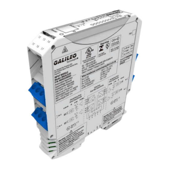
2. Product type This manual summarizes the use of the following product: Type MODC03B003 Input module intrinsically safe Picture is only a reference Warning! Advertisement! Read instruction's manual before operation. Lisez des instructions avant l’opération... -
Page 7: Intended Use
3. Intended Use 3.1. General If the equipment is used in a manner not specified by the manufacturer, the protection provided by the equipment may be impaired. The product is intended to be installed in a suitable external enclosure. The device is used in control and instrumentation technology for transfer of signals such as 20mA and 10V standard signals. -
Page 8: Mounting
4. Mounting Do not mount the device in the dust hazardous area. Maximum supply voltage 24Vdc. Operation ambient temperature -20°C to +45°C. Altitude up to 2,000 m. Maximum relative humidity 80 % for temperatures up to 31 °C decreasing linearly to 50 % relative humidity at 40 °C. The device fulfills a degree of Protection IP20 according to EN 60529 The Zener Barrier is secured to a DIN rail using a tab and screw. -
Page 9: Equipment Installation And Operation
5. Equipment installation and operation 5.1 Connections to the supply Danger! Danger to life from incorrect installation Incorrect installation of cables and connection lines can compromise the function and the electrical safety of the device. • Observe the permissible core cross-section of the conductor. •... -
Page 10: Equipment Operation
The DIN rail connector is integrated into the DIN rail. The bus connector has 5 positions for energy supply and data transmission. It connects several zener barrier modules, which are mounted on the DIN rail. Equipment Operation The barrier should be connected into the circuit while it is unpowered. The voltage through the barrier under normal operation should not exceed the rated Uo voltage. -
Page 11: Fuse Operation
6. Fuse operation There is a fuse inside the Zener Barrier that is rated for 40 mA. If the current at the input to output exceeds 40 mA by an Input or Output short, the fuse will be blown. Since the fuse is underneath the epoxy, if it is ever blown the Zener Barrier will need to be completely replaced. -
Page 12: Equipment Maintenance And Service
Compliance with the following precautionary measures is vital to ensure safe and reliable operation: Check all equipment packaging for transportation damage. Report any damage to the transporter and to GALILEO Technologies The equipment should be used only under the specified operating conditions and must be protected against excessive dust and mechanical stress (shock, vibration, etc.). -
Page 13: Disconnecting Circuits
Disconnecting Circuits 1. Disconnect the field circuit. 2.Removing the Device. Removing the Device To disconnect the power supply & Modbus communication first remove the M4 screw from tab with an Allen and then with a flat head screw driver by inserting the screw driver head in steel tab on the DIN rail side and pulling or prying to overcome the spring’s force the module will be remove. -
Page 14: Handling And Storage, And Transportation
9. Handling and storage, and transportation If the instrument is to be stored or transported for an extended period of time, please follow these safety precautions: The temperature should be maintained between –20 °C and +70 °C [–4 °F and 158 °F]. Contamination must be prevented from entering the unit. -
Page 15: Datasheet
11. Datasheet Input Module Intrinsically Safe Features Assembly • 4-channel Intrinsically Safe settable • 24VDC supply • Communication Modbus RS485 Function This Input Module intrinsically safe transfers Analog signals from 4-20mA, 0-10V, PT1000, DI. Convert to digital signal, store and send by protocol Modbus RS485. - Page 16 Technical data General specification Type 4-channel Intrinsically Safe settable Input Electrical specification Nominal resistance 330 Ω Fuse rating 40mA Main Input Connection Terminals 1-,2+ (Power) Terminals 3A, 4B, 5- ( RS485 Modbus ) Supply voltage Rated Current 40mA Hazardous area connection Terminals 8, 11, 14, 17 Uo Connection Terminals 7, 10, 13, 16 In...
- Page 17 1.5uF 2.0mH Lo/Ro 583uH/ Ω Maximum safe voltage 250 V (AC/DC)
-
Page 18: Electrical/Electromechanical Drawings
12. Electrical/Electromechanical Drawings... -
Page 19: Electrical Wiring Drawings
13. Electrical wiring Drawings... -
Page 20: Customer Service
14. Customer Service For additional information or in case of problems, contact the Operations and Services department. info@galileoar.com +54 9 11 4022-0827 +54 9 11 4712-8008 www.galileoar.com...
Need help?
Do you have a question about the MODC03B003 and is the answer not in the manual?
Questions and answers