Table of Contents
Advertisement
Quick Links
ALL phases of this installation must comply with NATIONAL, STATE AND LOCAL CODES
IMPORTANT — This Document is customer property and is to remain with this unit. Please return to service information pack
upon completion of work.
These instructions do not cover all variations in systems nor
provide for every possible contingency to be met in connec-
tion with installation. All phases of this installation must
comply with NATIONAL, STATE AND LOCAL CODES.
Should further information be desired or should particular prob-
lems arise which are not covered sufficiently for the purchaser's
purposes, the matter should be referred to your installing dealer
or local distributor.
A. GENERAL
▲
WARNING:
for use by individuals possessing adequate backgrounds of
electrical and mechanical experience. Any attempt to
repair a central air conditioning product may result in
personal injury and or property damage. The manufac-
turer or seller cannot be responsible for the interpretation
of this information, nor can it assume any liability in
connection with its use.
NOTE: AMERICAN STANDARD HAS ALWAYS RECOM-
MENDED INSTALLING AMERICAN STANDARD AP-
PROVED MATCHED INDOOR AND OUTDOOR SYSTEMS.
THE BENEFITS OF INSTALLING APPROVED MATCHED
SYSTEMS ARE MAXIMUM EFFICIENCY, OPTIMUM PER-
FORMANCE AND BEST OVERALL SYSTEM RELIABILITY.
Check for transportation damage after unit is uncrated. Report
promptly, to the carrier, any damage found to the unit.
To determine the electrical power requirements of the unit, refer
to the nameplate of the unit. The electrical power available must
agree with that listed on the nameplate.
B. LOCATION AND PREPARATION OF THE UNIT
1. When removing unit from the pallet, notice the tabs on the
basepan. Remove tabs by cutting with a sharp tool as shown in
Figure 2 (see page 2).
2. The unit should be set on a level support pad at least as large
as the unit base pan, such as a concrete slab. If this is not the
application used please reference ALG-APG0*-EN (*latest revi-
sion number).
3. The support pad must NOT be in direct contact with any
structure. Unit must be positioned a minimum of 12" from any
wall or surrounding shrubbery to insure adequate airflow. Clear-
ance must be provided in front of control box (access panels) & any
other side requiring service access to meet National Electrical
© 2005 American Standard Inc. All Rights Reserved
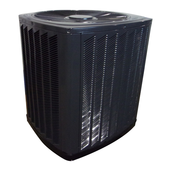
Condensing Units
2A7C3030-060A3/4000A
Models:
This information is intended
1
5 FT. ABOVE UNIT — UNRESTRICTED
Code. Also, the unit location must be far enough away from any
structure to prevent excess roof run-off water from pouring directly
on the unit. When choosing the location of the unit(s), sound
transmission through air and refrigerant lineset should be taken
into consideration. It is recommended to locate unit(s) away from
areas (bedrooms, etc.) where such sound could be objectionable.
4. The top discharge area must be unrestricted for at least five (5)
feet above the unit.
5. When the outdoor unit is mounted on a roof, be sure the roof will
support the unit's weight. Properly selected isolation is recom-
mended to prevent transmission to the building structure.
6. The maximum length of refrigerant lines from outdoor to
indoor unit should NOT exceed sixty (60) feet.
7. If outdoor unit is mounted above the air handler, maximum lift
should not exceed sixty (60) feet (suction line). If air handler is
mounted above condensing unit, maximum lift should not exceed
sixty (60) feet (liquid line).
Since the manufacturer has a policy of continuous product
and product data improvement, it reserves the right to
change design and specifications without notice.
11-AC19D1-1
Advertisement
Table of Contents

Related Manuals for American Standard 2A7C3000A


Summary of Contents for American Standard 2A7C3000A
- Page 1 National Electrical Since the manufacturer has a policy of continuous product and product data improvement, it reserves the right to © 2005 American Standard Inc. All Rights Reserved change design and specifications without notice.
- Page 2 INSTALLER'S GUIDE Final refrigerant charge adjustment is necessary. Use the BASEPAN TAB REMOVAL Charging Information on Page 6 or in the unit Service Facts. 1. Determine the most practical way to run the lines. 2. Consider types of bends to be made and space limitations. NOTE: Large diameter tubing will be very difficult to rebend once it has been shaped.
- Page 3 INSTALLER'S GUIDE GAS LINE BALL SERVICE VALVE GAS LINE SERVICE VALVE 1/4 TURN ONLY COUNTERCLOCKWISE FOR FULL OPEN POSITION VALVE STEM UNIT SIDE OF VALVE PRESSURE TAP PORT GAS LINE CONNECTION SYSTEM EVACUATION NOTE: Since the outdoor unit has a refrigerant charge, the gas and liquid line valves must remain closed.
- Page 4 INSTALLER'S GUIDE 10. Replace liquid service pressure tap port cap and valve stem cap. These caps MUST BE REPLACED to prevent leaks. PIN IDENTIFICATION Replace valve stem and pressure tap cap finger tight, then tighten an additional 1/6 turn. 11. The gas valve can now be opened. For a ball type gas valve, open the gas valve by removing the shut-off valve cap and turning the valve stem 1/4 turn counterclockwise, using 1/4"...
- Page 5 INSTALLER'S GUIDE H. OPERATIONAL AND CHECKOUT PROCEDURES L. TROUBLESHOOTING TROUBLESHOOTING CHART — WHAT TO CHECK Final phases of this installation are the unit Operational and Checkout Procedures which are found in this instruction on page 8. To obtain proper performance, all units must be operated and charge adjustments made in accordance with procedures found on page 6 and in the Service Facts.
- Page 6 American Standard has always recommended installing American R-22 SUBCOOLING CHARGING TABLE Standard approved matched indoor and outdoor systems. DESIGN SUBCOOLING VALUES (°F) All 13 SEER American Standard split systems are ARI rated LIQUID with only TXV indoor systems. TEMP. The benefits of installing approved indoor and outdoor split (°F)
- Page 7 INSTALLER'S GUIDE 2A7C3 OUTLINE DRAWING NOTE: ALL DIMENSIONS ARE IN MM (INCHES). MODELS BASE FIG. 2A7C3030A 832 (32-3/4) 829 (32-5/8) 756 (29-3/4) 5/16 137 (5-3/8) 86 (3-3/8) 210 (8-1/4) 79 (3-1/8) 508 (20) 2A7C3036A 832 (32-3/4) 829 (32-5/8) 756 (29-3/4) 137 (5-3/8) 86 (3-3/8) 210 (8-1/4)
- Page 8 12. Operate complete system in each mode clearance and smooth operation ....[ ] to insure safe operation........[ ] Technical Literature - Printed in U.S.A. American Standard Inc. Pub. No. 11-AC19D1-1 Troup Highway Tyler, TX 75707-9010 P.I. 9/05...
Need help?
Do you have a question about the 2A7C3000A and is the answer not in the manual?
Questions and answers