Table of Contents
Advertisement
ALL phases of this installation must comply with NATIONAL, STATE AND LOCAL CODES
IMPORTANT — This Document is customer property and is to remain with this unit. Please return to service information pack
upon completion of work.
These instructions do not cover all variations in systems
nor provide for every possible contingency to be met in
connection with installation. All phases of this installa-
tion must comply with NATIONAL, STATE AND LOCAL
CODES. Should further information be desired or should par-
ticular problems arise which are not covered sufficiently for the
purchaser's purposes, the matter should be referred to your
installing dealer or local distributor.
A. GENERAL
The following instructions cover 2A7A5, 2A7A4, 2A7A2, & 2A7A1
Condensing Units.
NOTE: The 2A7A4, 2A7A2,& 2A7A1 outdoor units, except
for the 5 ton models, may be used with indoor units
equipped with Thermostatic Expansion Valve or Accutron™
Flow Control Check Valve (F.C.C.V.) assembly for refriger-
ant flow control only. The 2A7A5 & all 5 ton outdoor units
must be used with indoor units equipped with Thermo-
static Expansion Valve only.
Check for transportation damage after unit is uncrated. Report
promptly, to the carrier, any damage found to the unit.
To determine the electrical power requirements of the unit, refer
to the nameplate of the unit. The electrical power available must
agree with that listed on the nameplate.
B. LOCATION & PREPARATION OF THE UNIT
1. When removing unit from the pallet, notice the tabs on the
basepan. Remove tabs by cutting with a sharp tool as shown in
Figure 2 (see page 2).
2. The unit should be set on a level support pad at least as large
as the unit base pan, such as a concrete slab. If this is not the
application used please reference ALG-APG0*-EN (*latest revi-
sion number).
3. The support pad must NOT be in direct contact with any
structure. Unit must be positioned a minimum of 12" from any
wall or surrounding shrubbery to insure adequate airflow.
Clearance must be provided in front of control box (access
panels) & any other side requiring service access to meet
National Electrical Code. Also, the unit location must be far
enough away from any structure to prevent excess roof run-off
water from pouring directly on the unit. When choosing the
location of the unit(s), sound transmission through air and
© 2005 American Standard Inc. All Rights Reserved
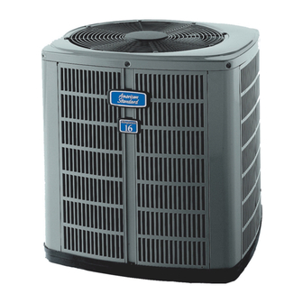
Condensing Units
Models :
2A7A5024-048, 2A7A4018-060,
2A7A2018-060 & 2A7A1018-060
TOP DISCHARGE — UNRESTRICTED
1
5 FT. ABOVE UNIT
refrigerant lineset should be taken into consideration. It is
recommended to locate unit(s) away from areas (bedrooms, etc.)
where such sound could be objectionable.
4. The top discharge area must be unrestricted for at least
five (5) feet above the unit.
5. When the outdoor unit is mounted on a roof, be sure the roof
will support the unit's weight. Properly selected isolation is
recommended to prevent transmission to the building structure.
6. The maximum length of refrigerant lines from outdoor to
indoor unit should NOT exceed sixty (60) feet.
7. If outdoor unit is mounted above the air handler, maximum
lift should not exceed sixty (60) feet (suction line). If air handler
is mounted above condensing unit, maximum lift should not
exceed sixty (60) feet (liquid line).
8. Locate and install indoor coil or air handler in accordance
with instruction included with that unit.
NOTE: Refer to "Refrigerant Piping Software" Pub. No.
32-3312-0*, and "Refrigerant Piping Manual" Pub. No.
32-3009-0* (the position of the * denotes latest revision
number).
Since the manufacturer has a policy of continuous product
and product data improvement, it reserves the right to
change design and specifications without notice.
11-AC11D2-5
Advertisement
Table of Contents

Subscribe to Our Youtube Channel
Related Manuals for American Standard 2A7A1018A


Summary of Contents for American Standard 2A7A1018A
- Page 1 Since the manufacturer has a policy of continuous product and product data improvement, it reserves the right to © 2005 American Standard Inc. All Rights Reserved change design and specifications without notice.
- Page 2 INSTALLER'S GUIDE 4. Provide a pull-thru hole of sufficient size to allow both liquid and gas lines. BASEPAN TAB REMOVAL 5. Be sure the tubing is of sufficient length. 6. Uncoil the tubing — do not kink or dent. 7. Route the tubing making all required bends and properly secure the tubing before making connections.
- Page 3 INSTALLER'S GUIDE LIQUID LINE SERVICE VALVE GAS LINE SERVICE VALVE BRASS GAS LINE BALL SERVICE VALVE nitrogen to 350-400 psi. Use soap bubbles or other leak-checking methods to see that all field joints are leak-free! If not, release The Brass Gas Line Ball Service Valve is shipped in the closed pressure;...
- Page 4 INSTALLER'S GUIDE Table 1 — NEC Class II Control Wiring GAS LINE BALL SERVICE VALVE 24 VOLTS 1/4 TURN ONLY WIRE SIZE MAX. WIRE LENGTH COUNTERCLOCKWISE FOR FULL OPEN POSITION 18 AWG 150 FT VALVE STEM 16 AWG 225 FT. UNIT SIDE OF VALVE 14 AWG...
- Page 5 INSTALLER'S GUIDE TYPICAL FIELD WIRING DIAGRAMS PRINTED FROM B152901 P02 PRINTED FROM B152908 P02 NOTE NOTE PRINTED FROM B152903 P02 PRINTED FROM B152907 P03 W2 present only on 2 stage W2 present only on 2 stage thermostat and furnace thermostat and furnace Notes: 1.
- Page 6 INSTALLER'S GUIDE 2A7A5, 2A7A4, 2A7A2, & 2A7A1 OUTLINE DRAWING NOTE: ALL DIMENSIONS ARE IN MM (INCHES). MODELS BASE FIG. 2A7A1018A 1045 (25-1/2) 502 (19-3/4) 476 (18-3/4) 149 (5-7/8) 19 (3/4) 89 (3-1/2) 16 (5/8) 460 (18-1/8) 2A7A1024A 1045 (25-1/2) 502 (19-3/4)
- Page 7 INSTALLER'S GUIDE MOUNTING HOLE LOCATION NOTE: ALL DIMENSIONS ARE IN MM (INCHES). NOTE: For model base size, see table on page 6. From Dwg. 21D152989 Rev. 1 Pub. No. 11-AC11D2-5 PAGE 7...
- Page 8 2 Check only necessary if heating unit is used for indoor section and wiring has been disturbed during installation of cooling equipment. 3 When applicable. Technical Literature - Printed in U.S.A. American Standard Inc. Troup Highway Tyler, TX 75707-9010 PAGE 8 Pub.
Need help?
Do you have a question about the 2A7A1018A and is the answer not in the manual?
Questions and answers