Advertisement
Quick Links
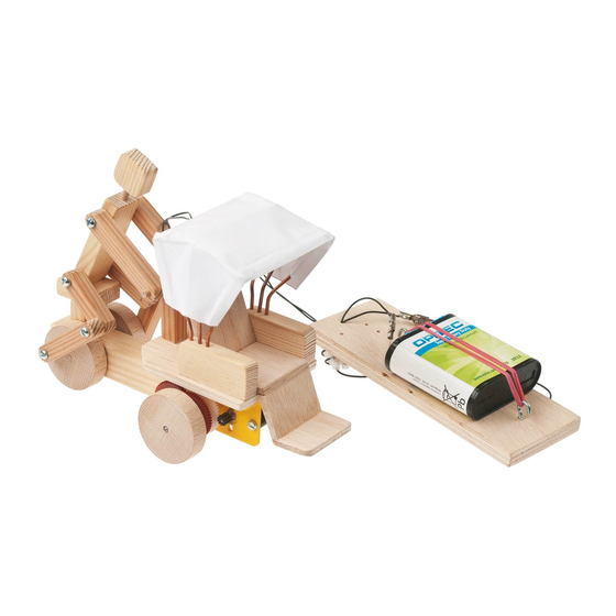
R i c k s h a w
E101887#1
1 0 1 . 8 8 7
r e m o t e
The OPITEC range of projects is not intended as play
toys for young children.They are teaching aids for
young people learning the skills of Craft, Design and
Technolo- gy.These projects should only be underta-
ken and tested with the guidance of a fully qualified
adult. The finished projects are not suitable to give to
children under 3 years old. Some parts can be swallo-
wed. Dan- ger of suffocation!
w i t h
c o n t r o l
Please Note
c a b l e
1
Advertisement

Related Manuals for Opitec 101.887


Summary of Contents for Opitec 101.887
- Page 1 Please Note The OPITEC range of projects is not intended as play toys for young children.They are teaching aids for young people learning the skills of Craft, Design and Technolo- gy.These projects should only be underta-...
- Page 2 1. Product Information: Article: Cable controlled vehicle in project in pack format. Use: In Design Technology, Key stage 4. 2. Material Information: 2.1 Material: Pine ( Coniferous) softwood. Beech ( Deciduous ) hardwood. Wood should be relatively dry before working. Working: The wood will need to be sawn, drilled, filed and sanded.
- Page 3 3. Tools: Wood files / rasps: Choose the correct grade of file or rasp according to the work in hand. Use needle files for small slots and notches Note! Use a sand paper and block on all flat surfaces and loose sheet on curves.
-
Page 4: Connector Block
4. Parts list: Part Material Quantity Size Diagram Screws (Crosshead). Steel 2,9 x 9,5 mm Screws (Pan head) Steel 2,9 x 6,5 mm Screws (Roundhead) Steel 3 x 20 mm Screw (Roundhead) Steel 3 x 16 mm Washers Steel 3,2 mm Nuts Steel Machine screw... -
Page 5: Exploded Diagram
5. Exploded diagram: 6. Planning overview 6.1 Designing and making the individual parts for the drivers seat, driver and arm supports 6.2 Making the chassis 6.3 Making and mounting the rickshaw seat 6.4 Making the base and seat 6.5 Assembling the gear system 6.6 Mounting the rickshaw seat and arm supports 6.7 Making the rickshaw driver 6.8 Mounting the driver on the rickshaw... - Page 6 6.1 Designing and making the individual parts for the drivers seat, driver and arm supports etc. 6.1.1 Mark out the pine strip (2) 10 x 20 x 150mm as shown, saw into sections along the lines. Note The remaining piece (2f) may be slightly undersize due the thickness of the saw cuts. 20,0 30,0 65,0...
- Page 7 6.1.4 Round off the top corners on the arm supports (2e) as shown in the diagram, mark out and drill the three 2mm diameter x 10mm deep blind holes. 45,0 6.1.6 Sand all the parts (2a/2b/2c/2d/2f) 6.2 Making the chassis 6.2.1 Mark out and saw part (1) from the strip (1) 20 x 20 x 200mm.
- Page 8 6.3 Making and mounting the rickshaw seat 6.3.1 Mark out the plans as shown on the plywood sheets (5) 5 x 40 x 130mm and saw them out. 70,0 40,0 25,0 25,0 6.3.2 Curve the top of the seat back (5a) and then chamfer the base shown. 40,0 6.3.3 On part (5b) chamfer both ends to slope at an angle of approx 20 degrees as shown in the diagram.
- Page 9 6.3.4 Chamfer both parts of (5c) on the ends at 20 degrees.. Note Make sure that the ends are chamfered in the correct direction! 40,0 6.3.5 Angle (5d) on the bottom at 20 degrees and round the top corners as shown. 40,0 6.3.6 Now assemble and glue all the parts ( 5a / 5b/ 5c/ 5d) together to make up the seat as shown in the isometric drawing.
-
Page 10: Assembling The Gearbox
6.5 Assembling the gearbox 6.5.1 The marked holes in the side angle brackets (11) are used as follows: - Insert a machine screw (18) M3 x 35mm in each of the holes marked 1 / 2: - The motor is clamped between the slotted holes marked 3 - The axle (21) 3dia x 95mm is inserted in the hole marked 4 - The axle (5) 3 x 70mm is inserted in hole 5 6.5.2 Place the angle brackets (11) so that the right angled parts face outwards. - Page 11 6.5.6 Turn the chassis over and fit the gear box in position using 4 screws (13) so that it lies centrally under the chassis floor (see diagram) 6.6 Mounting the rickshaw passenger seat, and arm supports Glue the seat directly onto the front of the chassis (4) and add the side arms (2e) so that the holes in the arms are at the rear.
- Page 12 6.7 Making and assembling the rickshaw driver 6.7.1 Measure and saw out the pieces from a pine strip (3) sand all the ends and drill as shown in the diagram. Sand all the parts. 60,0 50,0 40,0 40,0 50,0 40,0 30,0 35,0 6.7.2 From the dowel (6) cut a length for the steering bar (6b) and piece for the neck 25mm long.
- Page 13 6.8 Mounting the driver on the rickshaw 6.8.1 Insert a screw (14) through the 3.5mm hole in the ankle (3c), place the figure on the seat and insert the screw into the 2mm hole in the wheel (8a) Tighten it so that the legs can still move freely. 6.8.2 Now centralise the figure on the steering bar so that the mounting post (3d) is in the middle of the chassis and the body is leaning forward.
- Page 14 6.9.2 Insert the ends of the roof frame (7) in the 2mm holes in the arms of the seat. Bend and adjust them so that they are about 20 degrees apart from each other. Bend back approx 20 degrees Bend forward approx 20 degrees 6.9.3 Cut out the shape of the roof using the pattern (12 / page 13) fold the tabs inward 6.9.4 Lay the roof over the frames and fold / glue the front and rear tabs over the frame...
- Page 15 6.10 Making the remote control unit (switch) 6.10.1 Cut the brass rod (28) in half and file the burr from the end. 6.10.2 Two double sections form the 12 section connector block and join them together by using the brass rods. (See diagram) 6.10.3 Cut two lengths one (33a) and the other (33b) from the insulated wire (33).
- Page 16 6.10.7 Screw in the eyes (25) so that they are positioned as shown in the diagram. 6.10.8 Insert the wires (33a / 33b) through the holes as shown. 6.10.9 Turn the plywood base (6) over .Place 3 washers (16) over the 3 holes in a row and hold them in place with screws (12).
- Page 17 7. Patterns Scale 1 : 1 Base (4) 80,0 65,0 Roof E101887#1...
Need help?
Do you have a question about the 101.887 and is the answer not in the manual?
Questions and answers