Table of Contents
Advertisement
Quick Links
PARTS LIST
Plywood
Plywood
Gearbox
Black cable
Red cable
Battery holder
Micro switch
LED red
Screws
Machine screws
Machine screws
Nuts M4
Washers
Gear, ø4mm hole, 13 teeth
Gears, ø4mm hole, 38 teeth
Reducers
E111666#2
111.666
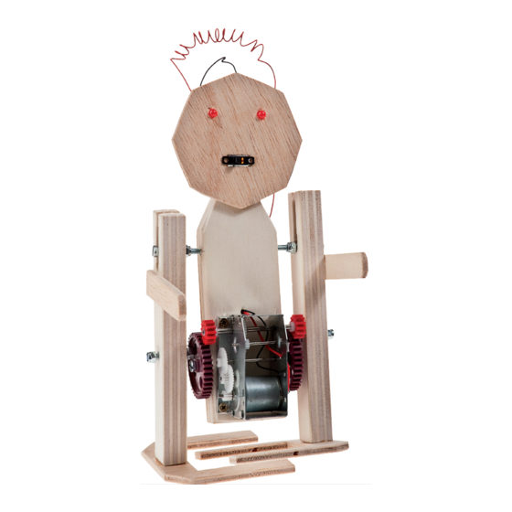
O P I - R o b o R 3 O 3
The OPITEC range of projects is not intended as play toys for young
children.They are teaching aids for young people learning the skills of
Craft, Design and Technolo- gy.These projects should only be underta-
ken and tested with the guidance of a fully qualified adult. The finished
projects are not suitable to give to children under 3 years old. Some
1
1
1
1
1
1
1
2
8
2
4
6
10
2
2
2
Necessary tools
Fretsaw
Ruler,pencil
Sandpaper
Wood glue
Screwdriver, slot and crosshead
Holemaker
Machine vice
Spannerl M4
Wire strippers
Side cutters
Soldering iron
Instant glue
Drills ø3,4,5
Countersink 90°
Metal saw
Hot air gun
Please Note
parts can be swallowed. Dan- ger of suffocation!
150x100x15 Body ,legs
250x100x5 Head,arms,feet
Drive
500 Wiring
Battery
19x6 Switch
ø5 Eyes
12x3 Fixing for foot, battery holder and
gearbox
M4x40 Leg fixing
M4x30 Leg fixing
M4 Fixing
M4 Fixing
ø15 Drive
ø40 Drive
4/3 Drive
1
2
3
4
5
6
7
8
9
10
11
12
13
14
15
16
1
Advertisement
Table of Contents

Related Manuals for Opitec OPI-Robo R3O3


Summary of Contents for Opitec OPI-Robo R3O3
- Page 1 Metal saw Hot air gun Please Note The OPITEC range of projects is not intended as play toys for young children.They are teaching aids for young people learning the skills of Craft, Design and Technolo- gy.These projects should only be underta- ken and tested with the guidance of a fully qualified adult.
- Page 2 INSTRUCTIONS 1. Trace the patterns for the body and legs ( Page 5) on to the plywood sheet (1) Use a macine vice to hold the body when drilling theside holes 15/20 mm deep. It importnat that these holes are drilled opposite each other otherwise the robot will not walk correctly! Trace the body and arms ( See page 7) on to the plywood sheet (2) Sand to finish Drill the 3mm holes and countesink 2mm deep as shown in the plan...
- Page 3 INSTRUCTIONS 6. Glue the arms ( Dia 4) under the opening in the legs. Glue the legs with the countersink underneath, and leave to dry well. Glue the second part in a mirror image to the first. Fix the feet from underneath with screws (9) Insert a machine screw (10) in the top opening in the legs and fix with a stop Dia.
- Page 4 INSTRUCTIONS 8. Note: Dia.10 Arrange the legs, so that the machine in thelarge gears, which drive the legs, are set at 180 degrees. ( Dia 10) Dia. 11 Mount the motor and gearbox (3) with the two small gears (14) on the front of the body with 4 screws (9) The small gear must mesh with the larger gear (15) (Teeth engage).
- Page 5 INSTRUCTIONS Wiring: Note: The wire connections can be twisted together but it is better if they are soldered. 12. - Join the anode legs of the LEDs together (Solder or twist ) - Take the red lead from the battery holder (6) cut it to ca. 20mm long and then remove the insulation and tin the end. - Cut a 100mm length of red cable (5) remove the insulation from both ends and tin the wire ends.
- Page 6 E111666#1...
- Page 7 INSTRUCTIONS Pattern Body,Legs M 1:1 Drilling pattern Gear (16) E111666#2...
- Page 8 E111666#1...
- Page 9 INSTRUCTIONS Pattern Head,arms,feet M 1:1 E111666#2...
Need help?
Do you have a question about the OPI-Robo R3O3 and is the answer not in the manual?
Questions and answers