Table of Contents
Advertisement
Quick Links
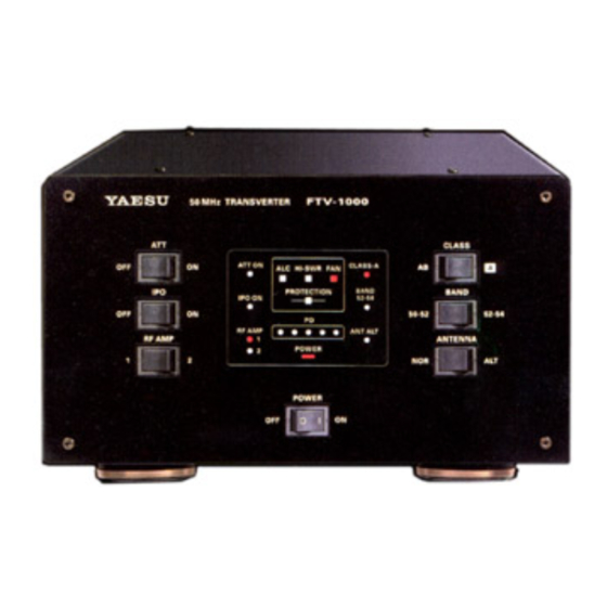
50MHz Transverter
FTV-1000
Operating Manual
VERTEX STANDARD CO., LTD.
4-8-8 Nakameguro, Meguro-Ku, Tokyo 153-8644, Japan
VERTEX STANDARD
US Headquarters
10900 Walker Street, Cypress, CA 90630, U.S.A.
YAESU EUROPE B.V.
P.O. Box 75525, 1118 ZN Schiphol, The Netherlands
YAESU UK LTD.
Unit 12, Sun Valley Business Park, Winnall Close
Winchester, Hampshire, SO23 0LB, U.K.
VERTEX STANDARD HK LTD.
Unit 5, 20/F., Seaview Centre, 139-141 Hoi Bun Road,
Kwun Tong, Kowloon, Hong Kong
FTV-1000 Operating Manual
Advertisement
Table of Contents

Subscribe to Our Youtube Channel
Related Manuals for Yaesu FTV-1000


Summary of Contents for Yaesu FTV-1000
- Page 1 P.O. Box 75525, 1118 ZN Schiphol, The Netherlands YAESU UK LTD. Unit 12, Sun Valley Business Park, Winnall Close Winchester, Hampshire, SO23 0LB, U.K. VERTEX STANDARD HK LTD. Unit 5, 20/F., Seaview Centre, 139-141 Hoi Bun Road, Kwun Tong, Kowloon, Hong Kong FTV-1000 Operating Manual...
- Page 2 FTV-1000 Operating Manual...
- Page 3 1.8 and 54 MHz, and especially on the six meter band. Thank you for your investment ion the FTV-1000! We recommend that you read this manual thoroughly, so as to understand fully the features and the operating procedures that will ensure that you get the most out of your leading-...
-
Page 4: Front Panel Controls & Switches
This is the main ON/OFF switch for the FTV-1000. in the Class-A mode, the maximum output power will When you turn the FTV-1000 on, the PA section of be reduced to approximately 50 watts. Operating SSB the MARK-V FT-1000MP will be disabled automatically, in Class-A yields an ultra-clean signal waveform. -
Page 5: Display Indicators
This red indicator lights up when receiver front-end jack is selected. preamplifier “2” is selected. POWER This red indicator lights up when the FTV-1000 is This red indicator lights up when an abnormally high turned on. ALC (Automatic Level Control) voltage is detected. -
Page 6: Rear Panel Controls & Connectors
DC POWER IN Jack This RCA jack provides for input of ALC voltage This is the power input jack of the FTV-1000. Con- from the VL-1000 Linear Amplifier, for control of the nect the DC power cable from the FP-29 AC power MARK-V FT-1000MP’s drive level. - Page 7 This switch activates an input RF power attenuator, to attenuate excessive input power from an exciter by 6 dB. This switch should normally be set to the “off” position when using the FTV-1000 with the MARK-V FT-1000MP. PLUG/CONNECTOR PINOUT DIAGRAMS...
- Page 8 1000’s “TX IN” jack and MARK-V’s “TRV” jack. The other connection cable, having a Gray RCA plug, is the ALC cable which connects between the FTV-1000’s “ALC” jack and MARK-V’s “EXT ALC” jack. This cable is designed for carrying of DC voltage, and does not guarantee the 50-Ohm impedance needed for optimum drive power transfer to the FTV-1000.
- Page 9 Interconnections FTV-1000 / MARK-V FT-1000MP / VL-1000 FTV-1000 Operating Manual Page 7...
-
Page 10: Operation
52 MHz ~ 54 MHz, set the BAND switch of the FTV-1000 to the “52-54” position. 4. Turn on the FTV-1000, you will now be operating on the 50 MHz band. The MARK-V FT-1000MP’s frequency display will still be on 28 MHz; however, you can use the transceiver’s... - Page 11 (200 Watts) may be used. the transceiver’s keypad. Note, however, that 7. The FTV-1000 is designed for use into a 50 Ohm you must enter “ [ 2 ] – [ 8 ] ” as the “MHz” part of antenna system.
- Page 12 VL-1000 L PERATION WITH THE INEAR MPLIFIER Operation of the FTV-1000 in conjunction with the The operating procedure, when using the VL-1000 Linear Amplifier is basically identical to that transverter, is the same as when just operating the when using the amplifier with the MARK-V FT-1000MP MARK-V FT-1000MP (alone) with VL-1000.
-
Page 13: Specifications
30 VDC (approx.) Rx (no signal) 0.5 A – Tx (200 W) 0.5 A 14.5 A Dimensions (WxHx D): 9.8” x 5.4” x 13” (248 x 136 x 332 mm) Weight (approx.): 16.5 lb (7.5 kg) FTV-1000 Operating Manual Page 11... - Page 14 Note Page 12 FTV-1000 Operating Manual...
- Page 15 FTV-1000 Operating Manual...
- Page 16 Copyright 2002 VERTEX STANDARD CO., LTD. All rights reserved. No portion of this manual may be reproduced without the permission of VERTEX STANDARD CO., LTD. Printed in Japan 0203L-BK FTV-1000 Operating Manual...
Need help?
Do you have a question about the FTV-1000 and is the answer not in the manual?
Questions and answers