Advertisement
Quick Links
ASSEMBLY INSTRUCTIONS
Before You Begin:
Please identify all component parts and hardware pieces required before you begin. Carefully remove all of the
components from the packaging and set aside for assembly. Assemble on a soft surface to prevent scratching during
assembly.
Tighten all components securely before use. Failure to do so may result in personal injury.
DO NOT use any sharp objects to open plastic wrapped components as damage to product or componenets may result.
CHOKING HAZARD - Small Parts. Adult Assembly Required.
DO NOT ALLOW CHILDREN TO CLIMB ON FURNITURE
Serious or fatal injuries can occur from furniture tipping over. You must install Tipping Restraint Hardware (where
included) to help prevent the unit from tipping and causing accidental injury, instability, death or damage. The tipping
restraint is intended only as a safety measure, it is not a substitute for proper adult supervision.
To help prevent furniture from tipping over it must be permanently attached to the wall. Anti-Tip Safety Wall Straps
suitable for the unit weight and wall materials (if not included) should be purchased and installed.
Online Assembly Instructions:
Customer Service Email: CustomerExperience@belnick.com | phone:866-552-2810
http://ftp.flashfurniture.com/AssemblyInstructions/GC-MBLK65-WH-GG.pdf
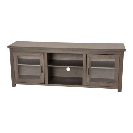
GC-MBLK65-BK-GG/GC-MBLK65-GY-GG/GC-MBLK65-WH-GG
65" Tr
TV Stand for up to 80" TVs
Assembly Time
Load Bearing
LBS
LBS
LBS
LBS
LBS
Thank you for your purchase!
Door
60 min
200 LBS
LBS
LBS
30 LBS
LBS
Advertisement

Related Manuals for Flash Furniture GC-MBLK65-BK-GG


Summary of Contents for Flash Furniture GC-MBLK65-BK-GG
- Page 1 To help prevent furniture from tipping over it must be permanently attached to the wall. Anti-Tip Safety Wall Straps suitable for the unit weight and wall materials (if not included) should be purchased and installed. Online Assembly Instructions: http://ftp.flashfurniture.com/AssemblyInstructions/GC-MBLK65-WH-GG.pdf Customer Service Email: CustomerExperience@belnick.com | phone:866-552-2810 GC-MBLK65-BK-GG/GC-MBLK65-GY-GG/GC-MBLK65-WH-GG...
- Page 2 Have a Question/Concern? Quality products and first-class customer service are the cornerstone of long-lasting consumer relationships. We strive toward excellence in all we do and want you to be completely satisfied with your purchase. Please contact our exceptional Customer Experience Agents at the email address or phone number shown below to assist you with any product questions or issues before requesting a return.
- Page 3 PARTS Cam Lock Covers Top Plate Left Front Fascia 32+1 (1) (11) 3.5*14 Right Front Fascia Bottom Plate (2) (12) 36+1 Back Panel Screws Left Side Panel Left Rear Fascia (3) (13) Door Handle Bolts Right Side Panel Right Rear Fascia (4)...
- Page 4 STEP 1 Screw-In Pegs Screws B*32 Door Strike Plates A*18 Dowel Pegs (6) Right Inner Support Fascia Top Plate (7) (1) (5) *2 Inner Supports (8) (2) Front Upper Brace (12) Right Front Fascia (4) Right Side Panel (14) Right Rear Fascia (3)...
- Page 5 STEP 3 Arrow Side Toward Receiver Hole Cam Lock Screw-In Peg (13) Receiver Hole STEP 2C: Ensure Cam Locks (Part C) are inserted in holes with open side facing outwards toward receiver hole for Screw-In pegs (Arrow Side). Insert Screw-In Pegs on the Left Side Rear Fascia (Part 13) into the Cam Locks (Part D) on the Left Side Panel.
- Page 6 STEP 5 STEP 5: Insert Cam Locks (Part C) into the Upper Front Panel (Part 8)and ensure the arrow side is facing outwards. Slide the Screw-In Pegs on the Left and Right Side Panels into the Cam Lock Receiver Holes in the Bottom Plate and Upper Front Panel (Part 8).
- Page 7 STEP 7 STEP 7: Ensure Cam Locks (Part C) are inserted in holes with open side facing outwards toward receiver hole for Screw- In pegs (Arrow Side). Slide Inner Supports (Part 5) onto Long Screw-In Pegs on the bottom plate. Turn the Cam Locks (Part D) clockwise to tighten.
- Page 8 STEP 9 STEP 9: Insert Cam Locks (Part C) into holes with arrow side pointing outwards. Insert preassembled Screw-In Pegs on Left Fascia (Part 7)and Right Fascia (Part 6) into the Receiver Holes and turn Cam Locks clockwise to tighten. (6)...
- Page 9 STEP 11 STEP 11A: Attach Hinges (Part J) to the Front Doors (Part 15) using (8) 3.5 Screws (Part E) Hinges Door Handle Screws Door Handle (15) Door Handle Screws STEP 11B: Attach Door Handles (Part H) to the Front Doors (Part 15) using (4) Door Handle Screws (Part G) Door Handle (15)...
- Page 10 STEP 13 I*12 Shelf Holders (17) I (16) (17) STEP 11: Insert Shelf Holders (Part I) into holes at the desired height then place the Left & Right Shelves (Part 17) and the Middle Shelf (Part 16) onto Shelf Holders STEP 14 Back Panel Screws STEP 14:...
Need help?
Do you have a question about the GC-MBLK65-BK-GG and is the answer not in the manual?
Questions and answers