Table of Contents
Advertisement
Quick Links
Advertisement
Table of Contents

Related Manuals for CST/BERGER CST202


Summary of Contents for CST/BERGER CST202
- Page 1 INSTRUCTION MANUAL Electronic Total Station CST202 CST205...
- Page 2 CST/Berger Electronic Total Station User’s Guide T ha n k you fo r s e l e ct in g t he CST / B e rge r E l e ct ro ni c Tot a l St a t ion . For t he best pe r fo rm an ce of t he inst r um en t, pl eas e re ad t his o pe rato r ’s...
-
Page 3: Table Of Contents
CONTENTS READ THIS FIRST 1. PRECAUTIONS FOR SAFE OPERATION 2. PRECAUTIONS 3. NOMENCLATURE AND FUNCTION 3.1 Parts of the instrument 3.2 Mode diagram-default set up 4. BASIC OPERATION 4.1 Basic key operation 4.2 Display functions 4.3 Display symbol PREPARATION BEFORE MEASUREMENT USING THE BATTERY 5.... - Page 4 Inputting the height of instrument and target 12.3 12.4 3-D coordinate measurement ADVANCED MEASUREMENT 13. SETTING-OUT MEASUREMENT 13.1 Distance setting-out measurement Coordinates setting-out measurement 13.2 14. OFFSET MEASUREMENT 14.1 Distance offset measurement 14.2 Angle offset measurement 15. MISSING LINE MEASUREMENT 15.1 Measuring the distance between 2 or more points 15.2...
- Page 5 22.1 Observation condition 22.2 Instrument configuration 22.3 Allocating key function 22.3.1 Defining softkeys 22.3.2 Registering a softkeys allocation Recalling a softkeys allocation 22.3.3 22.4 Unit setting ADJUSTMENT 23. SETTING THE INSTRUMENT CONSTANT 23.1 Tilt zero point error check and adjustment 23.1.1 Checking tilt zero point error 23.1.2...
-
Page 6: 1. Precautions For Safe Operation
1. PRECAUTIONS FOR SAFE OPERATION General Warnings Using the instrument near areas that contain high levels of dust, ash, combustible materials or in poorly ventilated areas may result in damage due to explosions. Do not attempt to service or repair instrument without proper training. Fire, shock or severe burns might occur due to disassembly or improper assembly. - Page 7 Power supply Do not use voltage other than the specified power supply voltage. Additionally do not use damaged power cords, plugs or loose outlets. Fire or electrical shock could result. Do not use third party cords or chargers as fire or instrument damage may occur.
-
Page 8: 2.Precautions
2.PRECAUTIONS Precautions concerning water and dust resistance Do not put the instrument in the water. The instrument conforms to IPX4, so the normal rain can not damage to the instrument, but improper use near water can severely damage the instrument resulting in costly repairs. Ensure that the battery is properly mounted and locked in the instrument. - Page 9 The CST/Berger Total Station is a precision instrument. Care must be taken when using this instrument. Please avoid shock or jolts to the instrument as they may negatively affect the calibration of the instrument.
-
Page 10: 3.Nomenclature And Function
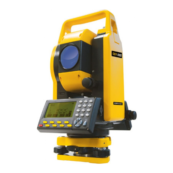
3.NOMENCLATURE AND FUNCTION 3.1 Parts of the instrument Handle Handle Sighting collimator securing screw Objective lens Battery Optical plummet Horizontal clamp Operation panel and fine motion screw Leveling foot screw Tripod clamp Telescope eyepiece Telescope and focus focusing knob Vertical clamp and Plate level fine motion screw Display... -
Page 11: Mode Diagram-Default Set Up
3.2 Mode diagram-default set up. Record mode REC/Dist. data Meas mode 【REC】 99°43′13″ MEAS 120°09′12″ MODE MEAS 【ESC】 99°43′13″ 120°09′12″ Menu mode DIST HSET 0SET MENU RESE MENU 1. Coordinate 【MENU】 2. S-O 【MEAS】 【ESC】 3. Resection 4. MLM Status screen 5. -
Page 12: 4.Basic Operation
4.BASIC OPERATION 4.1 Basic key operation 1.Power Key Power on :press 【 】 。 Power off :press 【 】, hold on 2 second. 2.Function key 【F1】~【F4】 : Select the function of matching the soft keys. 【ESC】 :Cancel the input data or return to the previous screen. 【SFT】... - Page 13 Example 1:Input file name “FTS” (1) Press【SFT】to come in the inputting letters mode, there will be the letter “a” displayed on the right of the screen. (2) Press 【2】three times, and then input the “F”。 (3) Press【 】 to move the curser to the right, press 【7】 twice and input the letter “T”.
-
Page 14: Display Functions
4.2 Display functions Status screen Total Station Instrument series Ver 3.5 Software version NO. 000001 Instrument No. MEAS CNFG Meas mode screen Battery power MEAS Distance Keys status Vertical angle Compensation 99°43′13″ Horizontal angle Page number 120°09′12″ DIST HSET 4.3 Display symbol In the Meas mode , the symbol meaning:... -
Page 15: 5.Using The Battery
5.USING THE BATTERY This instrument has the charger and battery of itself. The voltage of the battery is 7.2V. Please charge it before measurement. Please read the operation manual carefully before you use it. 5.1 Charging procedure (1) Connect the battery to the charger. (2)... -
Page 16: Installing Battery
5.4 Installing battery Fig.1 Fig.2 1. Press the button down and place the battery into the groove in the instrument. 2. Release button and press button upward.. 5.5 Removing battery Press the button down and take battery out of groove. 5.6 Battery power display There is a display on the screen that can be used to check the status of the battery power. -
Page 17: 6.Setting Up The Instrument
6.SETTING UP THE INSTRUMENT Caution: Mount the battery in the instrument before performing this operation because the instrument will tilt slightly if the battery is mounted after leveling. (1) Make sure the legs are spaced at equal intervals and the head is approximately level. -
Page 18: 7.Focussing And Target Sighting
(5) Centering the instrument with optical plummet: Adjust the eyepiece of the optical plummet telescope to the user’s eyesight. Move the instrument by loosening adjusting screw. Coincide image of the point on the ground with the center mark of the optical plummet telescope. Carefully move the instrument in order to make it steady. -
Page 19: 8.Power On
8.POWER ON (1) When the power is switched on, you will hear a buzzer. A self-check is run to make sure the instrument is operating normally. The instrument number and the software number will be displayed, and it will display “V angle set 0”. (2)... -
Page 20: 9. Function In The Star Key(*) Mode
9.FUNCTION IN THE STAR (★)KEY MODE At any mode, pressing 【SFT】 and 【★】 can enter the star key mode. In this mode you can do this: 【F1】——on / off the light of the screen. 【F2】——power on / off the laser plummet.(for instruments with laser plummet) 【F3】——on / off tilt angle compensation. -
Page 21: Checking The Memory Quickly
9.2 Checking the memory quickly 1.Press 【MEM】to display the status of memory. Job:The current job. Mem. status Recs:the number of records in the Job: JOB01 current job. Recs: Recs free:The number of the free record 【MEM】 Total: 15216 blocks can be used to store data in the Recs free:... -
Page 22: 10. Angel Measurement
10.ANGLE MEASUREMENT • Please refer to section: “21.2 record the angle measurement data”, to learn about recording measurements 10.1 Measuring the horizontal angle between two points Use the “0 SET” function to measure the included angle between two points. The horizontal angle can be set to 0 at any direction. -
Page 23: Setting The Horizontal Angle To A Required Value
10.2 Setting the horizontal angle to a required value 1.You can reset the horizontal angle to a required value and use this value to find the horizontal angle of a new target. Operating Keys Display 1. Sight the first target and then press in the first page of the 【HSET】... - Page 24 2. Pressing 【HOLD】performs the same function as above. Before this operation, you should define the horizontal hold function 【HOLD】 in the Meas mode. See “22.3.1 defining softkeys”. Operating Keys Display 1. Turn the instrument to the desired Hz angle using the Hz tangent and fine motion MEAS knob.
-
Page 25: Selecting The Direction Of Horizontal Angle (Hal/Har)
10.3 Selecting the direction of horizontal angle(HAL/HAR) The CST/Berger Total Station can read and display angles in the HAR right mode (angles right) or the HAL left mode (angles left). Before doing this, you should define the 【R/L】keys in the Meas mode. See “22.3.1 defining softkeys”. -
Page 26: 10.4 % Slope
10.4 % Slope The total station can display the % slope as well as vertical angle. Before this operation, you should define the【A/%】 in the Meas mode. See “22.3.1 Defining Softkeys”. Operating Keys Display 1. Press【A/%】 ,the % slope of the vertical angle will be displayed on ZA line MEAS as pictured to the right. -
Page 27: Horizontal Angle Repetition
10.5 Horizontal angle repetition To find the horizontal angle with greater precision, perform repetition measurement. 2 n d T a r g e t ( F S ) 1 s t T a r g e t ( B S ) 3 r d m e a s . -
Page 28: Outputting Angle Measurement Data
Display Operating Keys 4.Sight the target point 1 again, and press 【OK】. HARp: 30°00′00″ Reps: Avg: 30°00′00″ 【OK】 Take 1st target 5.Sight the target point 2 again, press 【OK】The added value of the horizontal HARp: 60°00′02″ angle is displayed on the first line Reps:... -
Page 29: 11. Distance Measrement
11. DISTANCE MEASUREMENT 11.1 EDM Settings Complete the following EDM settings before the distance measurement: Atmospheric correction factor Target Type Station Height and Target Height if required Prism constant correction value Distance measurement mode 1. Atmospheric correction factor To perform higher accuracy measurements, it is necessary to find the atmospheric correction factor from even more accurate temperature and pressure measurements and perform an atmospheric correction. - Page 30 2. Prism constant correction value Reflective prisms each have their prism constant (PC). Before measurement, you must set the prism constant correction value of the prism you are using. This instrument’s prism constant correction value has been set to “0” by default. (CST Prisms are either “0” or “-30”) 3.
- Page 31 Operating Keys Display 4.Press 【 】 【 】 or press 【PAGE】 directly to come to the temperature line EDM set of the second page, and input Temp<°C> the temperature 25 °C. 【 】 Pres<hPa> 1013 【 】 ppm: 0PPM 5.Press 【 】/【 】 to move cursor to the air pressure line and enter 1013, EDM set the ppm data is then...
-
Page 32: Returned Signal Checking
11.2 Returned signal checking Check to make sure that sufficient reflected light is returned by the reflective prism sighted by the telescope. This function comes in handy when using in conjunction with making long distance measurements. Note: In short distance measurement, even though the center of the reflective prism and the reticle are slightly misaligned, “*”... -
Page 33: Outputting Distance Measurement Data
Operating Display Keys 1. Sight Target as normal practice dictates. 2. To take measurement, press 【DIST】 from Dist. the Meas Mode Screen. When the Shot PC measurement starts, EDM information ppm = 0 (distance mode, prism constant 【DIST】 Mode: Fine r correction value, atmospheric STOP correction factor) is displayed and... -
Page 34: 12.Coordinate Measurement
12.COORDINATE MEASUREMENT Using the coordinate measurement application will enable the user to determine the 3-dimensional coordinates of a target position based on the Inst. Stn., Inst. Hgt., Tgt. Hgt., and back sight data. EDM setting should be done before coordinate measurement. (Please see “11.1 EDM settings”). -
Page 35: Inputting Instrument Station Coordinate
12.1.1 Inputting instrument station coordinate from keyboard Operating Keys Display 1.In the second page of Meas Mode, press 【CRD】 to display coordinate COORD measurement menu. 1.Observation Selecting “1. Coordinate” in 2.Stn. data 【CRD】 Menu Mode can perform the 3.Stn. orient same function. -
Page 36: Reading In Registered Coordinate Data
12.1.2 Reading in registered coordinate data The coordinate data registered in the memory in advance can be recalled by pressing 【READ】when inputting coordinates. Known point data, coordinate data in the current job and coordinate data in any job file can be read in. Operating Keys Display... -
Page 37: Azimuth Angle Setting
12.2 Azimuth angle setting The azimuth angle of the backsight point can be set by inputting the angle directly or by calculating from coordinates of the back sight point and the instrument station. Operating Keys Display 1.Select “3. Stn.orient” in <COORD> menu, and press 【... -
Page 38: Inputting The Height Of Instrument And Target
Display Operating Keys 3. Input the coordinates of the backsight point and press 【OK】. Set H angle/BS When you wish to read in and set N<m>: 248.695 coordinate data from memory, press E<m>: 176.254 【READ】.(Please see “12.1.2 Z<m>: Reading in registered coordinate 【OK】... -
Page 39: 3-D Coordinate Measurement
12.4 3-D COORDINATE MEASUREMENT The instrument user may determine the coordinates of a target points based on the station and backsight data along with rod and target heights. The coordinate values of the target are calculated using the following formula. N1=N0+S×sinZ×cosAz E1=E0+S×sinZ×sinAz Z1=Z0+S×cosZ+ih-th... - Page 40 Display Operating Keys 1. Sight the prism at the target point, In COORD <COORD> menu, select 1.Observation “1. Observation” and press 【 】to 2.Stn. data start measurement. 【 】 3.Stn. orient 4.Ins.h&Tgt.h The coordinate value of the target is displayed. COORD.
-
Page 41: Distance Setting-Out Measurement
13. SETTING-OUT MEASUREMENT (Stake Out) Setting out is the process of measuring a point (set out point) and comparing it to the required point data from the input data, plans or designs. The difference between the data input to the instrument (the set-out data) and the measured value can be displayed by measuring the horizontal angle, distance or coordinates of the sighted point. - Page 42 Operating Keys Display 1. Sight the reference direction in Face 1. Reference direction Instrument Station 2. From the second page of the Meas Mode , press 【0SET】two times MEAS to set the Horizontal angle to “0” (pressing 【0SET】 one time will cause 99°43′13″...
- Page 43 Operation Keys Display .Press 【OK】 to enter the setting-out S-O H observation screen. dH:horizontal distance difference. -119°23′18″ 【OK】 dHA: horizontal angle difference 0°00′00″ MODE 】 to enter the setting-out .Press 【 leading screen. The horizontal angle difference between the target and the S-O H point to be set out is displayed on the -119°...
- Page 44 Operating Keys Display 10. When the measurement is completed, the horizontal distance difference is displayed on the third S-O H line and the arrow displays 0°00′01″ → ← which direction the target should be -15.346m ↑ moved from the instrument. 119°23′19″...
-
Page 45: Coordinates Setting-Out Measurement
13.2 Coordinates Setting-out Measurement Setting-out coordinates measurement is used to set out the point whose coordinates is known. After inputting the coordinates for the point to be set out, the instrument calculates the setting-out horizontal angle and horizontal distance and stores them in the memory. By selecting the horizontal angle and then the horizontal distance setting-out functions, the required coordinate location can be set out. - Page 46 Operating Keys Display 1. On the third page of the Meas Mode Screen, press 【S-O】to enter the <S-O> menu. 1.S-O data Selecting “2. S-O” in the Menu Mode 2.S-O obs. will perform the same function. 3.Stn.data 2. Select “3. Stn.data” to input the ↓4.Stn.orient instrument station data.
- Page 47 Operating Keys Display 5. After the coordinates are entered, press [OK]. The distance and the horizontal S-O H & HA angle of the point to be set out are H<m>: 226.4854 calculated and displayed on the screen. 【OK】 79°43′37″ If the prism height has to be changed. Press 【HT】and re-enter the prism height before the measurement.(Please see “12.3 inputting the height of...
- Page 48 8. Move the prism upward and downward until the value displayed on the fourth S-O Coord. ▼ line is 0m. ← 0°0′0″ When the height difference approach ↑↓ 0.000m 0m,two arrows will be displayed. 0.000m When all the values displayed on the MODE DIFF STOP...
- Page 49 Operating Keys Display 1.Press 【EDM】 in the first page of the Meas Mode. EDM set Mode: Fine s. 【EDM】 C&R crn: OFF 2. Press 【 】 / 【 】 or press 【PAGE】 directly to move the cursor to the scale factor line. EDM set Scale F:...
-
Page 50: 14.Offset Measurement
14.OFFSET MEASUREMENT Offset measurements are performed when a target cannot be positioned directly on a point or when one needs to find the angle and distance of a point that can not be seen. It is possible to find the distance and angle to a point you wish to measure by positioning a prism and pole on a point that is slightly “off”... - Page 51 Operating Keys Display 1. Set the offset point close to the target point and measure the distance between them, then set up a prism on the offset MEAS. point. Sight the offset point and press 265.437m 【DIST】 in the first page of the Meas mode 89°33′18″...
-
Page 52: Angle Offset Measurement
5. Press 【OK】. The distance and angle of the target point are calculated and Offset/Target displayed. 263.683m Press 【REC】to record the result. (Please see 89°53′10″ “21.1 Recording distance measurement 50°26′42″ 【OK】 data”). Press 【SFT】 to switch the screen display from distance values to coordinates values. - Page 53 Operating Keys Display 1. Set the offset point as close to the object to MEAS be measured as closely as possible, making 265.437m sure the distance from the instrument 89°33′18″ station to the target point & the height of 50°26′42″ the offset points and the target point are 【DIST】...
- Page 54 Operating Keys Display 5. Press 【SFT】, and the coordinate of the target point will be displayed. Offset/Target Select “3.Stn.data” in <Offset> menu to 162.276m 【SFT】 confirm the data of the instrument 208.365m station. 16.378m 6. Press 【SFT】to display the distance and angle of the target point again.
-
Page 55: 15. Missing Line Measurement
15. MISSING LINE MEASUREMENT The Missing Line Measurement (MLM) routine is used to measure the slope distance, horizontal distance, and horizontal angle from one point to another with one point being a reference point or starting point. This is done without moving the instrument. The last measured point may be switched to the starting point for continuous measurements. - Page 56 Operating Keys Display 2. Press【MLM】 in the third page of the Meas Mode to enter the missing line Measurement mode. 【MLM】 Obs.2nd target Select “4. MLM” in the Menu Mode to perform the same function. MOVE Sight the second target and press 【MLM】to begin observation.
-
Page 57: Changing The Starting Point
15.2 Changing the starting point Some times it is necessary to make the last measured point the new starting point. Operating Keys Display 1. Observe the starting position and target ▼V following steps 1 to 3 in “15.1 Measuring 27.354m the distance between 2 or more points”... - Page 58 3. Press 【YES】 to change the last measured point to the next starting position. Perform MLM following steps 2 to 3 in “15.1 Obs. 2nd target 【YES】 Measuring the Distance between 2 or more points” MOVE...
-
Page 59: Rem Measurement
16. REM MEASUREMENT The REM Routine is used to measure vertical distances where a target cannot be placed such as power lines, bridge heights and overhead cables. The height of the target is calculated using the following formula: Ht=h1+h2 h2=Ssinθ ×cotθ... - Page 60 3. Accurately sight the prism, press 【DIST】 MEAS in the first page of the Meas mode to begin 10.567m measurement. The measurement results 90°11′57″ 【DIST】 are displayed. Press 【STOP】to stop the 135°31′27″ measurement. DIST 4. Press 【REM】or select “5. REM” in the menu mode to come in the REM function screen.
-
Page 61: 17. Resection Measurement
17. RESECTION MEASUREMENT To determine the coordinates of an instrument station by performing multiple measurements of points whose coordinate values are known is the process of Resection. Entry Output Ni, Ei, Zi: Coordinates of N0,E0,Z0:station point coordinates known point Hi: Observed horizontal angle Vi:... -
Page 62: Calculating The Station Coordinate By Measuring 2 Known Points
17.1 Calculating the station coordinate by measuring 2 known point Keys Display Operating 1. In the third page of the Meas Mode, press 【RESE】to perform this function. Resection/PT-01 Selecting “3.Resection” in the menu N﹤m﹥: mode can also perform this function. E﹤m﹥: 【RESE】... - Page 63 5. When the two known points have been input and measured, the list of the known Resection points is displayed. 01:PT-01 Press 【 】 / 【 】 to move the cursor and 02:PT-02 select the known point. Press 【ADD】to add a known point for REOBS CALC resection.
-
Page 64: Calculating The Station Coordinate Using Multiple Known Points
17.2 Calculating the station coordinate using multiple known points Operating Keys Display 1. Following the steps described in“17.1 Calculate the station coordinates by Resection measuring two known points”, input and 01:PT-01 measure two known point, and then the 02:PT-02 list of the known points are displayed. REOBS CALC 2. - Page 65 Caution: In some cases it is impossible to calculate the coordinates of an unknown point if the unknown point and three or more known points are arranged on the edge of a single circle. If this occurs, take one of the following actions: a) Position the instrument in the best fit center of the points around the circle...
-
Page 66: 18. Area Calculation
18. AREA CALCULATION This function allows for the calculation of the area of land using three or more known points. The coordinates of the points can be specified by measuring the point, reading-in from memory, and entering directly. Input Output Coordinate:P1(N1,E1)... - Page 67 Keys Display Operating 1. Press 【Area】 in the Meas Mode or select Area calculation “6.Area Calcul.” In the Menu Mode to PT-01 come in this function screen. 【AREA】 N<m>: E<m>: READ 2. Sight the first point ,and press 【OBS】to begin measurement. When measurement Area calculation is finished, the measured values are PT-01...
-
Page 68: 19. Setting-Out Line
19. SETTING-OUT LINE The Setting Out Line Routine allows for the set out of a point along a baseline at a designated distance off the line as well as finding out the distance from a baseline to a measured point. 2nd Pt Slope Origin... - Page 69 Operating Keys Display 1. Press 【LINE】in the Meas mode to enter the menu mode come in <S-O LINE> S-O LINE menu. 1.Def.base line Select “4. Stn.data” to input the 2.Point instrument station data. Select “5.Stn. 3.Line orient” to set the azimuth angle. Select ↓4.Stn.data 【LINE】...
-
Page 70: Setting-Out Line Point
4. Press 【PT2】.Input the coordinate of the second point at baseline. Baseline 2nd pt. To recall the coordinate data registered in the N<m>: E<m>: memory, press 【READ】.(Please see “12.1.2 【PT2】 Reading in registered coordinate data”). Z<m>: Press 【REC】to record the coordinate data in READ the memory 5. - Page 71 Operating Keys Display 1. Select“2.Point” in <S-O LINE> menu Input the following items: Set-out line (1)Length: Distance along the baseline from Length<m>: the origin point to the position at Offset<m>: which a line extending from the required point intersects the baseline at right angles (X 【...
-
Page 72: Setting-Out Line
19.3 Setting-out line The Setting-out line “Line” measurement tells how far horizontally the measured point is from the baseline and how far vertically the measured point is from the connected line. The baseline can be offset in a horizontal direction if necessary. Before performing setting-out line “Line”, the baseline must be defined. - Page 73 Operating Keys Display 1. Select“3.Line” in <S-O LINE> menu. Input the offset value of the line to be Set-out line set-out. Offset: How much to move the baseline. Right Offset<m>: side indicates positive values and left lide indicates negative value. 2.
-
Page 74: Managing The Job File
20. OPERATION IN THE MEMORY MODE Memory mode MEMORY 1.JOB 2.Known data 3.Code 4.Memory status 5.Init.memory In Status screen, Press 【MEM】to enter the memory mode. In this mode, you can read data from job file, changing file name, delete or store job file, output data to computer; input coordinate data by hand or from computer, recall or delete the coordinate of known points, input ID codes for objects beforehand and then recall them in later measurement, etc. -
Page 75: Reviewing And Deleting Record In Job File
20.1.1 Reviewing and deleting record in job file Operating Keys Display 1.Select the job file in the job file list, and press【 】to come in the screen 【 】 of managing job file. 1.View 【 】 2.Comms output 【 】 3.Rename 4.Del 2.The records within the job file list on the... -
Page 76: 20.1.2 Changing Name Of A Job
20.1.2 Change name of a job Operating Keys Display 1.Select a job in the job list. Press【 】 to go to the screen for managing job files. 【 】 1.View 【 】 2.Comm output 【 】 3.Rename 4.Del 2. Select “3. Rename ” to go to the file name File rename input screen. -
Page 77: Deleting A Job
20.1.3 Deleting a job Operating Keys Display 1.Select a job in the job list. Press【 】to come in the screen of managing job file. 【 】 1.View 【 】 2.Comm output 【 】 3.Rename 4.Del 2. Select “4. Del”,and a confirmation screen view. -
Page 78: Outputting Job Data To Computer
20.1.4 Outputting job data to computer Operating Keys Display 1. Connect the total station to computer. Run TS-link communication software on 2. Select the job in the job list, and Press 】to go to the job management 【 【 】 screen. -
Page 79: Inputting Coordinate Data Of Known Point
20.2 Inputting coordinate data of known point The coordinate data of known points may be input and stored in the instrument’s memory. These coordinate data can be recalled when setting instrument station, inputting backsight point and setting-out points. The known point coordinate data and job file data are stored in the difference directories in the instrument’s memory. -
Page 80: 20.2.2 Inputting Coordinate Data Of Known Point From An
20.2.2 Inputting coordinate of known point from an external equipment By running TS communication software on a PC, coordinate data of known points can be entered and edited, and then sent to the total station. Before the attempting communication, set the communication parameters following the communication protocols. -
Page 81: Reviewing And Deleting Known Point Data
20.3 Reviewing and deleting known point data All the known point stored in the memory can be reviewed or deleted at any time by the user. Operating Keys Display 1. Select “2. Known data” from the Memory KNOWN DATA Mode and press 【 】. -
Page 82: Deleting All The Known Point Data
20.4 Deleting all the known point data This function will delete all the known point coordinate in the memory. Operating Keys Display 1. Select “2. Known data” in the main KNOWN DATA Memory Mode and press 【 】. 1.Key in coord. 【... -
Page 83: Inputting Codes
20.5 Inputting codes Point or ID codes may be entered in the memory of the instrument in advance. When recording instrument station or observation data, these codes can be recalled and read in. Codes should be unique point descriptions. Also, it is suggested that one code be called NOTE. -
Page 84: Reviewing And Deleting Codes
20.6 Reviewing and deleting codes It is possible to review and delete codes stored in the memory. Operating Keys Display 1. Select “3. Code” in the Memory Mode and press 【 】 to go to the <CODE> menu CODE screen. 【... -
Page 85: Displaying The Status Of Memory
20.7 Displaying the status of memory Operating Keys Display 1. Select “4.Memory status” in the memory mode and press 【 】. Memory status Jobs:The number of job files in the Jobs : memory. Known pts: Known pts:The number of known points 【... -
Page 86: 21. Recording Data In The Record Mode
21. RECORDING DATA IN THE RECORD MODE Pressing 【REC】on the second page of the Meas Mode Screen and you will go to the record mode. In this mode, you can store measurement data (distance, angle, coordinates and codes) in the memory of the instrument. 21.1 Recording distance measurement data In the record mode, distance measurement data, offset measurement data, etc, can be store in the current job file. - Page 87 4. Press 【REC】 to record the data marked with “*”. You will then be able to Input the follow items: (1) Point name (Maximum size:8) Rec >> No job (2) Code(Maximum size:8) Pt.: (3) Prism height Code: If no job file selected for storing the Tgt.ht:1.232 【REC】...
-
Page 88: Recording Angle Measurement Data
Operating Keys Display Check the input items, then press 【OK】 to store the measurement data in the REC/Dist. Data current job file and return to the step 1. 103.126m 【OK】 101°19′37″ 350°43′20″ MODE MEAS Press 【ALL】to perform distance measurement and automatically record the results. In this case, the point number is the last point number add one, the code and target height remain the same. - Page 89 Operating Keys Display 3. Sight the target and press 【MEAS】. The angle measurement results of the REC/Angle data target marked with “*” are displayed. 101°19′37″ 【MEAS】 *HAR 350°43′20″ 4. Press 【REC】 to record the measured results. Input the follow items: (1) Point name Rec >>...
-
Page 90: Recording Coordinate Measurement Data
21.3 Recording coordinate measurement data In the record mode, coordinate measurement data, offset measurement data, etc, can be store in the current job file. Again, it may be convenient to use 【ALL】 to perform automatic measurements and recording. The content of stored data includes coordinates, point name, code and height of the target. - Page 91 4. Press 【REC】 to record the measured results. Input the follow items: Rec >> JOB02 (1) Point name Pt.: (2) Code Code: (3) Prism height Tgt.ht:1.232 Press 【JOB】to change and select the VIEW current job. 【REC】 Press 【VIEW】 to check the records that have been stored within the current job file.
-
Page 92: 22. Changing The Parameter Settings
22. CHANGING THE PARAMETER SETTINGS This section explains parameter settings and how to change settings. Each item can be changed to meet your measurement requirements and remains until it is changed again, even when the power is cut off. 22.1 Observation Condition The items and their options listed in the following table can be set in Observation Condition setting. - Page 93 Operating Keys Display 2.Press 【CNFG】to enter the config mode. CONFIG 1.Obs.condition 【CNFG】 2.Instr.config 3.Key function 4.Unit 3. Select “1. Obs.condition” and press 】to go to the observation 【 condition setting screen. *Zenith V.obs Tilt crn 【 】 Coll. crn *1″ Ang.
-
Page 94: 22.2 Instrument Configuration
22.2 Instrument configuration The items and their options list in the following table can be set in Instrument Configuration setting. The option marked with “*” is factory setting. Items Options Explanation To save power, select whether to turn power supply Auto off off automatically if no key is pressed in twenty minutes. -
Page 95: 22.3 Allocating Key Function
22.3 Allocating key function It is possible to allocate the softkeys in Meas Mode Screens to suit the measurement conditions. The current softkey allocations are retained until they are revised again, even when the power is cut off. It is possible to register three sets of key function allocations: Def.1, Def.2 and Def.3 and these allocations can be recalled at anytime. - Page 96 To menu mode (coordinates measurement , setting-out measurement , resection 【MENU】 : measurement, missing line measurement , REM measurement , area calculation, offset measurement , repetition measurement, setting-out line) Set the instrument station height and target height 【HT】 Hold horizontal angle /release horizontal angle 【HOLD】...
-
Page 97: Registering A Softkeys Allocation
Press 【5】/【6】 to change the function 4. of this softkey. Key function 【5】 DIST HSET 【6】 0SET MENU Repeat step 3 to 4 until all required softkeys have been allocated. Press 【 】 to record the allocations 6. Key function and return to <Key function>... -
Page 98: Recalling A Softkeys Allocation
Select one of the three position as the 2. Key function softkey array to be registered and press 【5】 【 】. Register to Def.1 【6】 【 】 Press 【YES】.The softkey array is 3. Key function registered and the key function menu 1.Def.1 screen restored. -
Page 99: 22.4 Unit Setting
22.4 Unit setting The option Marked with “*” is the factory Default Setting. Operating Keys Display Select “4. Unit” and press 【 】to go to the unit setting screen. *deg Ang. unit Dist. unit 【5】 *℃ Temp. unit 【6】 *hPa Pres. -
Page 100: 23. Setting The Instrument Constant
23. SETTING THE INSTRUMENT CONSTANT The instrument constant will affect the accuracy of measurement result; therefore setting of these should be performed with special care. This should be done by a properly trained service technician. 23.1 Tilt zero point error check and adjustment If tilt angle compensation has been selected, the tilt zero point error will adversely affect vertical angle measurement. - Page 101 3.Select “1. Tilt offset” and press 【 】 Tilt offset to start adjustment. TILT Pressing 【0SET】 can set horizontal angle 350°19′22″ 【 】 to 0. <Step1> Take F1? 0SET 4. Sight the target point in Face 1. Wait for the TILT offset display of tilt value to stabilize, and then TILT...
-
Page 102: 23.2 Vertical Circle Index Error And Collimation Error Correction
23.2 Vertical circle index error and collimation error correction With this option, using direct and reverse observations, you can measure collimation error in your instrument so that the instrument can correct subsequent single face observations. The 0 index of the vertical circle of your instrument can be reset also, and the index error of the vertical angle measurement can be corrected. - Page 103 Accurately sight a target with a distance of 4. 30m or further in Face1, then press 【OK】 . V0 & Coll. crn Press 【CE】 to cancel the last operation 93°25′32″ and redo it. 350°19′22″ 【OK】 <STEP2>:Take F2? Loosen the horizontal clamp, rotate the top 5....
-
Page 104: 23.3 Setting Additive Constant And Multiple Constant Of Distance
23.3 Setting additive constant and multiple constant of distance In this setting, you can correct additive distance constant and multiple distance constant of the instrument. Operating Keys Display 1.Level instrument carefully, and then turn the power on. When the message to prompt Instr. - Page 105 Reference: Check the additive constant of the distance The additive distance constant of the instrument is adjusted before delivery. It is possible that this will deviate over time, use a baseline with a known precision distance to check the additive distance constant. If there is no baseline, perform these checks as follows.
-
Page 106: 24. Checks And Adjustments
24. CHECKS AND ADJUSTMENTS The total station is a precision instrument that requires fine adjustments. It must be inspected and adjusted before use so that it always performs accurate measurements. Using “24.1 Plate level and circular level”, Check to ensure that the bubbles are accurately in adjustment. -
Page 107: 24.2 Reticle
2 .Checking and adjusting the circular level ● Check Carefully level the instrument with the plate level. If the bubble of the circular level is centered properly at this time, adjustment is not required. Otherwise, proceed with the following adjustment. ●... -
Page 108: 24.3 Adjusting The Telescope Axis
③ Check if there is displacement while traveling along vertical reticle. If not, your done. 【NOTE】 :After you finish it , you should perform adjustment as follows: “24.3adjusting the telescope axis”, “23.1 Tilt zero point error check and adjustment” “23.2Vertical circle index error and collimation error. 24.3 Adjusting the telescope axis ●Check ①... -
Page 109: 24.4 Optical Plummet
24.4 Optical plummet ● Check ① Set up instrument over a point and line the optical plummet up with the center of the reference point. ② Rotate the instrument 180°or 200g around the vertical axis and check the center mark. If the point is properly centered in the center mark, adjustment is not required. Otherwise, adjust in the following manner: ●... - Page 110 25. BI-DIRECTIONAL COMMUNICATION The total station features bi-directional communication. It is possible for external devices to control the total station in order to perform measurements and get measurement results through this communication process. i.e. External Data Collectors. Before performing this function, define the softkey 【COMM】 in the Meas mode following the steps in “22.3 define the keys function”, then press 【COMM】...
- Page 111 (2)Set the horizontal angle: Ask:STX+S+A+zzzzzzz+CR Respond:X_ON “zzzzzzz” is required horizontal angle.(Example :1565342) (3)Read angle measurement data : Ask:STX+R+A+CR Respond:STX+R+A+yyyyyyy+zzzzzzz+CR if tilt over 3′, it will respond:STX+R+A+Eyyyyyy+Ezzzzzz+CR “yyyyyyy” is the vertical angle (Example:3595959) “Zzzzzzz” is the horizontal angle (Example:3595959) (4) Read distance and angle measurement data: Ask:STX+R+D+CR Respond:STX+R+D+xxxxxxx+yyyyyyy+zzzzzzz+CR If measurement is failed, it will respond:...
-
Page 112: 26.Maintenance
Make checks to the tripod to ensure that all screws and clamps remain in good working order. If you encounter any problem with the instrument, please contact CST/Berger or your nearest service facility. When storing the instrument for long periods of time, please remove batteries. -
Page 113: 27.Error Messages
27.ERROR MESSAGES Message Meaning What to do Out of range The instrument is tilted beyond Re-level the instrument or turn the vertical compensation off the tilt compensation in the range. (±3') bad conditions. if the message displays again, repair required. Calcul. - Page 114 Message Meaning What to do EDM wrong Displayed during the system Turn off the power and turn it running self-check, on again, if the message abnormality is detected in displays again, repair EDM. required. Bad memory There’s abnormality in internal Turn off the power and turn it memory system on again, if the message...
-
Page 115: 28. Total Station Specification Chart
28. TOTAL STATION SPECIFICATION CHART Model CTS02 CTS05 Telescope Length of Telescope 150mm Image Erect Objective Lens Aperture 45mm Magnification Field of View 1°30′ Resolving Power 4.0″ Shortest Sighting Distance 1.5m Stadia Ratio Stadia Constant Angle Measurement Method Raster Incremental Detecting Horizontal : Double Vertical :Single... - Page 116 CST/Berger Total Station Item List Description Quantity Note Total station Carrying case Plumb bob adjusting wrench Screwdriver Soft brush Lens cloth drier rain cover Tool bag manual Rechargeable battery charger Wrench S=1.5 Wrench S=1.3 Data Transfer Software Date cable...
Need help?
Do you have a question about the CST202 and is the answer not in the manual?
Questions and answers