Advertisement
Available languages
Available languages
Quick Links
Electronic Self-Leveling
Electronic Self-Leveling
Electronic Self-Leveling
Rotary Laser
Electronic Self-Leveling
Rotary Laser
Rotary Laser
Rotary Laser
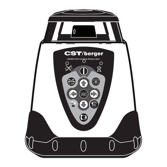
LMH600 Self-Leveling Rotary Laser
LMH600
LMH-CU
Instruction Manual
Manual de Instrucciones
Manuel d'Instructions
Manuale di Istruzioni
Bedienungsanleitung
Instruções de Utilização
models:
LMH600, LMH-CU
www.cstberger.com
Advertisement

Related Manuals for CST/BERGER LMH600


Summary of Contents for CST/BERGER LMH600
- Page 1 LMH600, LMH-CU Electronic Self-Leveling Electronic Self-Leveling Electronic Self-Leveling Rotary Laser Electronic Self-Leveling Rotary Laser Rotary Laser Rotary Laser LMH600 Self-Leveling Rotary Laser LMH-CU Instruction Manual Manual de Instrucciones LMH600 Manuel d’Instructions Manuale di Istruzioni Bedienungsanleitung Instruções de Utilização www.cstberger.com...
- Page 2 2 • LMH-SERIES...
- Page 3 LMH-SERIES • 3...
-
Page 4: Table Of Contents
Fig. 4 LMH600 Self-Leveling Rotary Laser LMH600 Self-Leveling Rotary Laser Fig. 5 Fig. 6 LMH600 Self-Leveling Rotary Laser Fig. 7 Fig. 8 LMH-CU Errors Fig. 9 X—AXIS ERROR Y—AXIS ERROR SPINDLE ERROR Fig. 10 LMH600 Errors X—AXIS ERROR “MORE” “MORE”... - Page 5 Laser class is indicated on the instrument. Repair and servicing of this laser are to be performed only by CST/berger or authorized service centers. This laser complies with all applicable portions of title 21 of the Code of Federal Regulations set by: the Dept.
- Page 6 LASER SAFETY WARNING: Be sure to read and understand all instructions in this manual before using this product. Failure to follow all instructions may result in hazardous radiation exposure, electric shock, fire, and/or bodily injury. CAUTION: Use of controls or adjustments or performance of procedures other than those specified in this manual, may result in hazardous radiation exposure.
- Page 7 FEATURES LMH600 Self-Leveling Rotary Laser LMH-CU LMH600 Low Battery Indicator Anti-Drift System Single Slope/Grade Dual Slope/Grade Dual-Beam Scanning Angle Feature Directional Head Positioning Variable Speed Rotation LayDown Auto-beam Positioning LMH-SERIES • 7...
- Page 8 LMH600 only) Battery Low LED Indicator Light Anti-Drift System LED Indicator LMH-CU Power ON/OFF LED Indicator Manual Grade Adjustment Buttons (LMH600) LMH600 5/8 - 11 Tripod Mounting Threads (for level work)/ Battery pack. Heavy-Duty Handle Vertical Beam (LMH600 only)
- Page 9 LMH-CU Fig. 1 LMH-SERIES • 9...
- Page 10 LMH600 Fig. 2 LMH600 Self-Leveling Rotary Laser 10 • LMH-SERIES...
- Page 11 APPLICATIONS Professional grade Accuracy and Durabillity for general construction and site preparation jobs. Including; LMH600 Self-Leveling Rotary Laser LMH600 Self-Leveling Rotary Laser • Grading and excavation • Porch and deck construction • Driveway paving • Exterior siding • Marking elevation •...
- Page 12 Press the (A) button. Allow the instrument to self-level. Setup a Benchmark. LMH600 Only – Set the Variable Speed Rotation (page 13) to the desired rotation speed of the laser head. Ideal speed for use with laser detector is 600 RPM.
- Page 13 1° per 4 seconds. After self-leveling, the instrument will begin operating in Rotation Mode. NOTE: The LMH600 will return to last mode of operation (i.e. sweep, spot, or rotation speed); however, does not retain grade information, NOTE: After self-leveling, the instrument will begin operating in Rotation Mode for LMH-C.
- Page 14 The default setting for ADS is user selectable. The default setting may be set to ADS ON or ADS OFF. When the instrument is OFF, press and hold the (C) button for LMH-CU, or for LMH600 hold (F) button, and then press the (A) button. Once the instrument is ON, turn the instrument off for 15 sec and then back ON.
- Page 15 When returning to normal operation the unit must be within its leveling range. Re-set the unit to a level position before pressing the MANUAL MODE button to the off position. Manual Grade Mode – Dual Axis Grade (LMH600 only) The dual grade function is ideal for general site grading, checking excavations, landscaping and drainage, and more (Fig.
- Page 16 REPLACING BATTERY If the battery is low, the LED will be illuminated on the front of the instrument. If the instrument operates erratically, try replacing the batteries (Fig.15). 1. Remove the battery tray by unscrewing the plastic nut around the mounting thread on the bottom of the instrument.
- Page 17 Repeat the above steps to ensure a correct reading. If the distance is greater than specified accuracy, you will need to calibrate the X axis. NOTE: For LMH600 Spot Mode can be used without detector if designed. Upright Position Calibration– X axis Model LMH-CU (Fig.16)
- Page 18 Calibration Mode, press the ADS button in order to turn OFF the corresponding LED. Laydown Position Peg Test – Z axis (LMH600 only) To test the Z axis, place the instrument on its back using the built-in trivet (control panel facing upward), 100 feet (30m) from a wall on a flat, level surface.
- Page 19 Laydown Position Calibration – Z axis (LMH600 only) Keep the instrument in its current position. Power OFF the instrument. Power ON the instrument while holding the (G) button down. You will know if Calibration Mode is activated when the Battery and Anti-Drift LEDs flash alternately.
- Page 20 SPECIFICATIONS LMH-CU LMH600 Laser Diode: 650 nm 635 nm Beam Type: Red Visible Laser ± 3/32-in. Horizontal Accuracy: (2.4mm) at 100-FT. (30m) Vertical Accuracy: ± 1/8-in. at 100-FT. (30m) (3mm) Electronic (up to ±3º) Electronic (up to ±5º) Leveling Type:...
- Page 21 For warranty and repair information, contact: Your Local Distributor, or CST/berger. For U.S., before returning the instrument to CST/berger, please call (815) 432-9200 for a Return Authorization Number from our Customer Service Department. This Warranty does not cover deficiencies caused by accidental damage, wear and tear, use other than in accordance with the manufacturer's instructions or repair or alteration of this product not authorized by CST/berger.
- Page 22 ELECTRONIC LASER DETECTOR Introduction The Universal Laser Detector aids in locating and targeting a visible or invisible beam emitted by a rotary laser; perfect for use in outdoor conditions, where sunlight and distance may make locating the beam more difficult. The laser detector LD400 includes a rod clamp which allows to mount the detector onto square, round or oval sighting rods.
- Page 23 Move the detector upward when the low beam indicator light is lit (with volume on, a slow pulsing audio tone is heard). Move the detector downward when the high beam indicator arrow is lit (with volume on, a rapid pulsing audio tone is heard). When the beam is level, the level beam indicator line will be lit and a solid audio tone will be heard.
- Page 24 REMOTE CONTROL RC700 Remote Control Operation (Fig. 23) - For model LMH600only This section covers the use of the remote control (Cat. #57-RC700). The remote controls all the functions except power, ADS, and calibration features, with a range of up to 100 feet (30m). Requires 2 ‘AA’...
- Page 25 Láser autonivelante electrónico Horizontal / Vertical, Plomada; Doble Inclinación manual Copyright© 2008 CST/berger. Derechos reservados. Toda esta información es propiedad de CST/berger. Este documento no debe ser copiado o reproducido sin el consentimiento escrito de CST/berger. SEGURIDAD Y ESPECIFICACIONES Es posible trabajar con el aparato sin peligro, sólo después de haber leído atentamente las instrucciones para el uso y las advertencias de seguridad, y siguiendo estrictamente las instrucciones.
- Page 26 PROCEDIMIENTOS DE OPERACIÓN SEGUROS ADVERTENCIA: Asegúrese de leer y comprender todas la instrucciones en este manual antes de usar este producto. El no seguir todas las instrucciones podrá resultar en exposición de radiación peligrosa, electrocución, incendio y/o heridas corporales. PRECAUCIÓN: El uso de controles, ajustes, o la ejecución de procedimientos diferentes a aquellos especificados en este manual podrán resultar en la exposición a radiación peligrosa.
- Page 27 CARACTERISTICAS LMH600 Self-Leveling Rotary Laser LMH-CU LMH600 LED indicador de carga de la batería Sistema de alarma anti movimento (ADS) Inclinación simple individual Doble inclinación simultánea Cabeza con plomada a techo Modo barrido 4 ángulos de apertura Rotación de la cabeza a ambos lados Velocidad de rotación...
- Page 28 Indicación LED de carga de las pilas. Indicación alarma antimovimiento (ADS) LMH-CU Interruptor ON/OFF (conexión / desconexión) LMH600 Interruptores ajuste inclinación manual (sólo LMH600) Tapa de las pilas / Base con rosca 5/8”x11 Asa muy robusta Cabeza con plomada (sólo LMH600) 28 • LMH-SERIES...
- Page 29 LMH-CU Fig. 1 LMH-SERIES • 29...
- Page 30 LMH600 Fig. 2 LMH600 Self-Leveling Rotary Laser 30 • LMH-SERIES...
- Page 31 Precisión y durabilidad profesional para la construcción en general y preparación de los diversos trabajos : • Nivelaciones y excavaciones LMH600 Self-Leveling Rotary Laser LMH600 Self-Leveling Rotary Laser • Construcción de solados, patios y terrazas. • Pavimentación de carreteras • Recubrimientos exteriores •...
- Page 32 Pulse el botón de encendido (A). Deje que la unidad se nivele automáticamente. Fije una marca de referencia. Para los modelos LMH600: fije el modo de rotación variable a la velocidad a la que quiera que gire el cabezal del láser. La velocidad ideal para el uso con receptor láser es de 600 RPM.
- Page 33 - el último modo seleccionado antes de apagarlo (por ej. Barrido, Punto Fijo, Rotación) = modelo LMH600. . NOTA: el LMH600 no guarda en memoria la inclinación manual. Busqueda de plomada vertical / LAY-DOWN (Modelo LMH600) Coloque la unidad en posición “tumbada” sobre una superficie nivelada lisa utilizando la asa, con el panel de control hacia arriba.
- Page 34 El usuario puede ajustar por defecto en ON o OFF. Con la unidad apagada, mantener pulsado el botón (C) (LMH-CU) o (F) (LMH600), y después apretar el botón (A). Cuando la unidad está encendida, apagarla durante 15 segundos y encenderla otra vez.
- Page 35 Dar tiempo a la unidad para reaccionar entre cambios de grados (Fig. 10). Modo posición línea (Modelo LMH600) En este modo, la unidad permite ajustar la posición de la línea vertical (plomada). Por ejemplo, si ha establecido una plomada y se da cuenta que está desviada hacia la derecha o izquierda del objetivo, use la Posición de la Línea para colocar la línea en su lugar sin tener que...
- Page 36 M M o o d d e e l l o o L L M M H H 6 6 0 0 0 0 Posición de línea será activado únicamente si la unidad es situada en posición de nivelación vertical (panel de control hacia arriba). En esta posición el láser puede trabajar en modo Rotación, Barrido, o Punto.
-
Page 37: Fig. 17
Comprobar de nuevo la precisión de la rotación horizontal repitiendo los pasos 1-4 de esta sección para asegurarse una comprobación precisa. NOTA: En los modelos LMH600 se puede comprobar la calibración en Modo Punto, sin detector. Calibración del error horizontal – Eje X No mueva el instrumento de su posición actual. - Page 38 Los botones (+) e (-) cambian los incrementos del eje. El botón (+) sube el rayo. N N O O T T A A : para LMH-CU pulsando el botón (B) cambiará entre los ejes X e Y para calibración. El LED manual indica eje X seleccionado.
- Page 39 Comprobación en la rotación vertical - Eje “Z” (sólo LMH600) Coloque la unidad en posición “tumbada” a 100 pies (30 metros) de una pared sobre una superficie nivelada lisa, con el panel de control hacia arriba y con un lado del instrumento hacia la pared.
- Page 40 DATOS TÉCNICOS LMH-CU LMH600 Diodo Láser: 650 nm 635 nm Rayo Láser: Rayo rojo visible ± 3/32-in. Precisión a (2.4mm) 30 m: Precisión vertical ± 1/8-in. a 30 m: (3mm) electrónica (Hasta ±3º) electrónica (Hasta ±5º) Autonivelación: Distancia con Hasta 610 m en diámetro el receptor láser:...
- Page 41 Cualquier reparación o reemplazo durante la vigencia de esta Garantía no afecta a su fecha de vencimiento. Dentro de lo autorizado por la legislación vigente, CST/berger no se obliga por esta Garantía a compensar pérdidas como resultado de deficiencias en el producto.
- Page 42 RECEPTOR LÁSER Introducción El receptor láser CST/berger ayuda a localizar y dirigir señales láser visibles y no visibles emitidas por un láser rotativo. Es perfecto para utilizar en condiciones de exterior donde la luz del sol y la distancia pueden hacer esta tarea más difícil.
- Page 43 Funcionamiento Encender la unidad presionando el interruptor ON/OFF. Los símbolos LCD parpadearán momentáneamente (Fig. 21) y los receptores de señal indicadora permanecerán encendidos Colocar el panel frontal del receptor láser hacia la dirección del láser rotativo. Mover lentamente el receptor láser hacia arriba o hacia abajo hasta que las flechas de la señal LCD receptora aparezcan y/o una señal de audio se escuche.
- Page 44 En el modelo LD-400 el detector acústico tiene tres selecciones, apagado, medio (105 dBA) y alto (+125 dBA). MANDO A DISTANCIA RC700 (Fig. 23) - Sólo para el modelo LMH600 Esta sección habla sobre el uso del mando a distancia (57-RC700).
- Page 45 Double pente manuelle. Copyright© 2008 CST/berger. Tous droits réservés. Les informations contenues dans le présent manuel appartiennent à CST/berger qui se réserve le droit d’apporter toute modification technique sans préavis. Interdiction de copier ou de reproduire le présent manuel sans avoir obtenu auparavant l’autorisation écrite de CST/berger.
- Page 46 PROCÉDURE DE SECURITE POUR L’ULISATION DE L’INSTRUMENT LASER AVERTISSEMENT: Assurez-vous de lire et comprendre toutes les instructions dans ce manuel avant d’utiliser ce produit. Ne pas suivre toutes les instructions peut entraîner l’exposition aux radiations dangereuses, des électrochocs et/ou des blessures corporelles. PRÉCAUTION: L’emploi de commandes, réglages ou la réalisation de procédures autres que ceux précisés dans ce manuel peut entraîner l’exposition aux radiations dangereuses.
- Page 47 Positionnez TOUJOURS l’outil laser d’une façon stable et sure. Si l’outil tombe, il peut être endommagé ou l’utilisateur peut être blessé. Utilisez TOUJOURS seul les accessoires recommandés par le fabricant de votre outil laser. L’emploi d’accessoires conçus pour d’autres outils laser pourrait entraîner des blessures graves. N’UTILISEZ PAS: cet outil laser dans tout autre but que ceux décrits dans ce manuel.
- Page 48 FONCTIONNALITÉS LMH600 Self-Leveling Rotary Laser LMH-CU LMH600 Témoin de charge de batterie Système Tilt Simple pente Double pente Double faisceau Fonction scanning Contrôle de rotation point par point Vitesse de rotation variable Positionnement automatique du point d’équerrage 48 • LMH-SERIES...
- Page 49 Bouton Marche/Arret LMH600 Boutons pour le réglage manuel de la pente (LMH600 uniquement) Emplacement des piles ou du pack accus et vis de montage sur trépied, filetage 5/8” – 11 Poignée de transport Faisceau visible vertical (LMH600 seulement) LMH-SERIES • 49...
- Page 50 LMH-CU Fig. 1 50 • LMH-SERIES...
- Page 51 LMH600 Fig. 2 LMH600 Self-Leveling Rotary Laser LMH-SERIES • 51...
- Page 52 : niveau laser idéal pour tous travaux dans le BTP et tous travaux d’aménagement préalables à la construction, tels : LMH600 Self-Leveling Rotary Laser LMH600 Self-Leveling Rotary Laser • Mivellement et excavation • Construction de porches et de ponts •...
- Page 53 Appuyez sur le bouton (A). Laissez l’instrument s’autoniveler. Définissez un « point de référence ». LMH600 uniquement - Définissez le mode Rotation variable sur la vitesse de rotation souhaitée (vitesse de rotation de la tête du laser). 600 RPM correspond à la vitesse idéale pour une utilisation avec un détecteur laser.
- Page 54 Une fois le calage terminé, l’instrument repasse en Mode Rotation, sur le modèle LMH-CU, dans le dernier Mode sélectionné avant de l’éteindre, sur le modèle LMH600(par ex., Balayage, Point Fixe ou Mode Rotation; toutefois il ne sauvegarde pas la pente d’information).
- Page 55 Mode Rotation (Modèle LMH600) Le mode Rotation permet de régler la vitesse de rotation de la tête. Cette caractéristique permet d’augmenter la visibilité du plan engendré par la rotation de la tête: on peut ainsi travailler aussi bien à l’horizontale qu’à la verticale.
- Page 56 OFF ou sur ON par défaut lorsqu’il allume le laser. Lorsque le laser est éteint, appuyez sur la touche «C» sur le clavier du LMH-CU (et sur la touche “F” du clavier du LMH600) sans la relâcher, puis appuyez sur «A». Une fois que le laser est allumé, éteignez-le pendant 15 secondes, puis rallumez-le.
- Page 57 D’INCLINAISON ». Laissez largement le temps à l’instrument de s’adapter aux modifications ou réglages effectués (Fig. 10). Position Ligne - Alignements et équerrages (Modèle LMH600) Cette fonction permet d’exécuter les alignements d’éléments verticaux, tels que piliers, façades continues ou parois en carton-plâtre, ou des alignements et des équerrages dans les intérieurs, de manière extrêmement rapide, sans devoir déplacer physiquement le laser.
- Page 58 PROCÉDURES DE SÉCURITÉ ÉLECTRIQUE AVERTISSEMENT: Les piles peuvent exploser ou avoir des fuites, et causer des blessures ou un incendie. Pour réduire ces risques : Suivez TOUJOURS toutes les instructions et tous les avertissements sur l’étiquette de la pile et l’emballage.
-
Page 59: Fig. 17
Vérifiez à nouveau l’exactitude de ces données en refaisant la procédure de 1 à 4. Si la tolerance est supérieure à la precision spécifiée, vous devez étalonner l’axe X. Remarque: Pour LMH600, le Mode Spot peut être utilise sans le détecteur. Étalonnage du positionnement vertical – axe X Laissez l’instrument dans son positionnement actuel. - Page 60 (Fig. 19). Si le faisceau laser ne s’aligne pas avec le fil à plomb, l’étalonnage de l’axe Z est nécessaire. Étalonnage du positionnement horizontal – axe Z - (Modèle LMH600) Laissez l’instrument dans son positionnement actuel. Mettez-le hors tension.
- Page 61 Vous devez ensuite répéter le test de positionnement de l’axe Z (points 1-3) afin de vous assurer que l’étalonnage effectué est correct. Vous pouvez effectuer ce test de positionnement en mode Étalonnage. DONNÉES TECHNIQUES LMH-CU LMH600 Diode laser: 650 nm 635 nm Couleur laser: Laser rouge ±...
- Page 62 ENTRETIEN Après usage, nettoyez toujours l’appareil avec un chiffon doux et sec pour éliminer toute trace d’humidité. N’utilisez ni détergents ni solvants agressifs. Si vous n’avez pas l’intention d’employer l’instrument pour longtemps, il est conseillé de le replacer dans sa mallette et d’en ôter les batteries. Contrôlez régulièrement l’état des piles. PROTECTION DE L’ENVIRONNEMENT Récupération des matières premières et non pas simple élimination des déchets.
- Page 63 Après diagnostique du Service Après Vente CST/berger, seul compétent à intervenir sur le produit défectueux, celui-ci sera réparé ou remplacé par un modèle identique ou par un modèle équivalent correspondant à l’état actuel de la technique, selon la décision de CST/berger qui en informera le distributeur.
- Page 64 DÉTECTEUR LASER UNIVERSEL Introduction Le détecteur laser universel permet de localiser et de cibler plus facilement un faisceau visible ou invisible généré par un laser rotatif: idéal pour un usage externe où les rayons du soleil et l’importance des distances peuvent rendre plus difficile la localisation du faisceau. Le détecteur laser est toujours équipé...
- Page 65 fonctionnalité de résolution du faisceau pour sélectionner l’un des paramètres suivants: le paramètre brut/faible (utilisé pour un nivellement approximatif ou pour la localisation initiale du point de nivellement plus précis) et le paramètre élevé (utilisé pour un nivellement très précis). Déplacez le détecteur vers le haut lorsque la flèche du bas est allumée (si le bouton du volume est sur marche, vous pouvez entendre une succession de brefs signaux sonores).
- Page 66 TÉLÉCOMMANDE RC700 (Fig.23) – Pour le modèle LMH600 uniquement La télécommande 57-RC700 contrôle toutes les fonctions de la nivelle à l’exception de la mise sous tension, de l’ADS, et du réglage. La télécommande peut être utilisée à une distance maximale de 30 m (100 pi) du laser et fonctionne avec 2 piles alcalines type AA.
- Page 67 Raggio a Squadro. Doppia pendenza manuale Copyright© 2008 CST/berger. Diritti riservati. Le informazioni contenute in questo manuale sono di proprietà della CST/berger, che si riserva di apportare modifiche tecniche senza preavviso. E’ vietato copiare o riprodurre questo manuale senza previo consenso scritto della CST/berger.
- Page 68 PROCEDURE OPERATIVE IN CONDIZIONI DI SICUREZZA AVVERTENZA: Vi preghiamo di leggere attentamente questo manuale di istruzioni prima di utilizzare il laser la prima volta. La mancata osservanza delle istruzioni può comportare un’esposizione a radiazioni pericolose, scosse elettriche e/o lesioni personali. ATTENZIONE: Il ricorso a controlli, regolazioni o procedure diversi da quelli indicati in questo manuale può...
- Page 69 CARATTERISTICHE LMH600 Self-Leveling Rotary Laser LMH-CU LMH600 Spia livello di carica della batteria Allarme di Spostamento Singola pendenza Doppia pendenza Doppio raggio Scansione Posizionamento del raggio fisso Velocità di rotazione regolabile Centramento automatico del punto a terra LMH-SERIES • 69...
- Page 70 Testa laser, autolivellante entro +/-5° LED livello batterie LED ADS LMH-CU LED di indicazione ON/OFF Pulsanti impostazione pendenza manuali LMH600 (solo LMH600) Base filettata 5/8”x11 (per lavori in orizzontale) / Pacco batterie Robusta maniglia di trasporto Raggio a squadro (solo LMH600) 70 • LMH-SERIES...
- Page 71 LMH-CU Fig. 1 LMH-SERIES • 71...
- Page 72 LMH600 Fig. 2 LMH600 Self-Leveling Rotary Laser 72 • LMH-SERIES...
- Page 73 APPLICAZIONI Grado di precisione professionale e affidabilità per le costruzioni generali e la preparazione del cantiere, includendo: LMH600 Self-Leveling Rotary Laser LMH600 Self-Leveling Rotary Laser • Pendenze e scavi • Verande e portici • Viali d’accesso • Guide esterne • Controllo delle quote •...
- Page 74 Premete il pulsante di accensione (A). Lasciate che lo strumento si autolivelli. Impostate un “Riferimento”. LMH600: Regolate la velocità di rotazione della testa. La velocità ideale per l’uso con un ricevitore è 600 RPM (giri al minuto). Leggete i valori relativi alla quota utilizzando il piano di luce laser come riferimento. Seguite le procedure di funzionamento del ricevitore riportate in questo manuale.
- Page 75 Non appena il laser è a livello, lo strumento comincerà a funzionare in Modo Rotazione. NOTA: Il laser LMH600 ritornerà all’ultimo Modo selezionato prima dello spegnimento (per es. Scansione, Punto Fisso, o Modo Rotazione); non è tuttavia in grado di memorizzare la pendenza eventualmente impostata.
- Page 76 A laser spento, tenete premuto il tasto (C) (LMH-CU) o il tasto (F) (LMH600), quindi premete il tasto (A). Una volta che il laser è acceso, spegnetelo per 15 secondi quindi accendetelo di nuovo. Se prima l’ADS era ON (OFF) come default, a questo punto sarà...
- Page 77 NOTA: Quando si ritorna al funzionamento Automatico, occorre che il laser sia in una posizione abbastanza livellata. Assicuratevi di questo prima di premere il tasto (C). Impostazione delle Pendenze – Doppia Pendenza (LMH600 ) La doppia pendenza è ideale per lavori di spianamento in generale, controlli di scavo, drenaggio, modellazione del territorio, etc…( Fig.
- Page 78 SOSTITUZIONE DELLE BATTERIE Quando le batterie sono scariche si accende il LED sul pannello frontale dello strumento. Se il laser non funziona in modo appropriato, sostituite le batterie (Fig.15). 1. Svitate la rondella di plastica posta attorno alla filettatura presente sulla base dello strumento ed estraete il piatto porta batterie.
-
Page 79: Fig. 17
Verificate di nuovo l’esattezza di questi dati ripetendo i punti da 1 a 4. Se la distanza è maggiore alle specifiche, l’asse X deve essere calibrato nel modo seguente. NOTA: Nei modelli LMH600 la calibrazione si può verificare in Modo Punto senza l’utilizzo del ricevitore. - Page 80 segni (A) e (B) (posizione C). Lo strumento NON reagisce agli input fino a che non è costretto a ri-livellarsi (ruotatelo e ricontrollate il punto (A). Se il segno (B) si trova sotto al segno (A) occorre dare input positivi, viceversa se (B) si trova sotto (A).
- Page 81 Verifica del Piano Verticale – Asse Z (Modello LMH600) Per controllare il piano verticale, appoggiate lo strumento sul pavimento o su una superficie abbastanza piana, ad una distanza di circa 30 m dalla base di una parete, in modo che la tastiera di controllo sia rivolta verso l’alto e un lato dello strumento verso la parete.
- Page 82 DATI TECNICI LMH-CU LMH600 Diodo laser: 650 nm 635 nm Raggio laser: Raggio rosso, visibile Precisione a 30 m: ± 2.4mm Precisione ± 3mm verticale a 30 m: autolivellamento elettronico autolivellamento elettronico Tipo di autolivellamento: (fino a ±3º) (fino a ±5º)
- Page 83 GARANZIA CST/berger , garantisce questo prodotto riguardo a difetti nei materiali o della manodopera per d d u u e e a a n n n n i i dalla data d’acquisto.
- Page 84 Caratteristiche (Fig.20) 1. Display LCD 2. Indicatore sonoro 3. Finestra di ricezione del raggio laser 4. Interruttore ON/OFF 5. Banda di precisione 6. Volume ON/OFF 7. Display LCD posteriore 8. Comparto batteria Display LCD (Fig. 21) 12. Freccia verso il basso 13.
- Page 85 Cura e manutenzione I ricevitori sono a tenuta di pioggia e di polvere. Pulire lo strumento utilizzando un panno morbido ed asciutto, per eliminare ogni umidità o sporco. Non utilizzare né detergenti, né solventi aggressivi. Se lo strumento non viene utilizzato per un lungo periodo, si consiglia di togliere la batteria. Specifiche Tecniche D D e e s s c c r r i i z z i i o o n n e e L L D D 4 4 0 0 0 0...
- Page 86 TELECOMANDO RC700 (Fig.23) – Solo per il modello LMH600 Il telecomando 57-RC700 controlla tutte le funzioni del laser, ad eccezione dell’accensione, dell’ADS e della calibrazione. Il telecomando può essere utilizzato fino ad una distanza massima di 30 m dal laser e funziona con due batterie alcaline tipo AA.
- Page 87 Horizontal/Vertikal mit Lotstrahl. 2 manuelle Neigungen Copyright © 2008 CST/berger. Alle Rechte vorbehalten. Die hier enthaltenen Angaben sind geistiges Eigentum von CST/berger und dürfen ohne Zustimmung von CST/berger weder verwendet, noch verändert werden Dieses Dokument darf ohne schriftliche Zustimmung von CST/berger weder kopiert noch anderweitig weiterverarbeitet werden.
- Page 88 VERFAHREN FÜR DEN SICHEREN BETRIEB ACHTUNG: Stellen Sie sicher, dass Sie alle in dieser Bedienungsanleitung enthaltene Anweisungen gelesen und verstanden haben, bevor Sie dieses Produkt verwenden. Nichtbeachtung der Anweisungen kann zu Gefährdung durch Strahlung, Stromschlag, Brand und/oder Körperverletzungen führen. VORSICHT: Die Anwendung von Bedienungs- und Einstellungselementen bzw. die Durchführung von Verfahren, die nicht in dieser Anleitung beschrieben sind, kann zur Gefährdung durch Strahlung führen.
- Page 89 GERÄTEMERKMALE LMH600 Self-Leveling Rotary Laser LMH-CU LMH600 Batterieanzeige Lichtanzeige beim Anti-Drift-System Einfache Neigung Zweifache Neigung Lotstrahl Scanning-Funktion Positionierung des Rotationskopfes Variable Rotationsgeschwindigkeit 4 unterschiedliche Geschwindigkeiten Automatische Positionierung des Lotstrahls im vertikalen Betrieb LMH-SERIES • 89...
- Page 90 S S Y Y M M B B O O L L E E Selbstnivellierender Rotationskopf (± 5°) LED – Batteriekapazitätsanzeige LED Ùberwachungsfunktion (ADS) EIN/AUS Schalter LMH-CU Manuelle Neigungseinstellung (LMH600) Batteriefach / 5/8“x11 Gewinde für LMH600 Stativbefestigung Schwerer Griff Lotstrahl (nur bei LMH600) 90 • LMH-SERIES...
- Page 91 LMH-CU Fig. 1 LMH-SERIES • 91...
- Page 92 LMH600 Fig. 2 LMH600 Self-Leveling Rotary Laser 92 • LMH-SERIES...
- Page 93 ANWENDUNGEN Professionelle Genauigkeit und Beständigkeit für alle Arbeiten auf der Baustelle. Zudem für: • Neigungsarbeiten und Aushub LMH600 Self-Leveling Rotary Laser LMH600 Self-Leveling Rotary Laser • Bau von Terrassen • Teerarbeiten • Anbauten • Höhenmarkierungen • Garten- und Landschaftsbau A A c c h h t t u u n n g g : : E E i i n n r r i i c c h h t t u u n n g g e e i i n n e e r r R R e e f f e e r r e e n n z z h h ö ö h h e e •...
- Page 94 Drücken Sie die Netztaste (A) und warten Sie, bis sich das Gerät einnivelliert hat. Markieren Sie eine Referenzhöhe. Nur für LMH600 - Stellen Sie mit Hilfe der Fernbedienung oder der Rotations- Geschwindigkeitstaste die gewünschte Drehzahl ein. Die ideale Drehzahl für Arbeiten mit einem Laserdetektor ist 600 U/min.
- Page 95 Bitte beachten Sie, dass der Rotorkopf schon vor Abschluss des Nivelliervorgangs zu rotieren beginnen kann. Die Nivelliergeschwindigkeit ist ca. 1° pro 4 Sekunden Nach dem Nivelliervorgang rotiert der Rotorkopf beim LMH-CU, der LMH600 geht in den zuletzt gewählten Arbeitsmodus (Rotations,- Scan-, Punkt-Modus; gilt jedoch nicht für Neigungseinstellung).
- Page 96 Wählen der Rotationsgeschwindigkeit (Modelle LMH600) Man kann die Rotationsgeschwindigkeit des Rotorkopfes erhöhen oder verringern, und dadurch eine gut sichtbare 360º Referenzebene erzeugen. Diese Funktion ist sowohl im horizontalen als auch im vertikalen Einsatz wählbar. Durch Drücken der (E) Taste, kann man die Geschwindigkeit von 600, 300, 150, bis 0 RPM einstellen.
- Page 97 Diese Funktion wurde eingeführt, um dem Bediener von einem möglichen Messfehler zu warnen. Grundsätzlich ist diese Funktion bei allen Modellen nach dem Einschalten aktiviert (kann aber vom Bediener geändert werden), sowohl im horizontalen als auch im vertikalen Einsatz (LMH600). (ca. 60 Sekunden nach dem Nivelliervorgang bzw. nach dem erneuten aktivieren dieser Funktion).
- Page 98 Ausrichten der vertikalen Ebene (Modelle LMH600) Nachdem Sie das Lasergerät auf dem Griff zum vertikalen Arbeiten aufgestellt und eingeschaltet haben, können Sie die Richtung der senkrechten Ebene oder des Lotstrahls wie folgt fein ausrichten. Diese Funktion ist nur aktiv, wenn das Bedienfeld nach oben zeigt.
-
Page 99: Fig. 17
Wiederholen Sie die Schritte 1-4 um sicher zu stellen, dass diese Ablesungen korrekt sind. Sollte der Abstand zwischen A und B größer sein als die spezifizierte Genauigkeit, dann muss die X Achse kalibriert werden. Achtung: Bei den Modellen LMH600 kann man zur Kalibrierung den Punkt Modus ohne Empfänger verwenden. Kalibrierung – X Achse Lassen Sie das Gerät in der momentanen Position und schalten Sie... - Page 100 Überprüfen Sie nun entsprechend dem Punkt “ Überprüfung Horizontale (X-Achse)“ die Einstellung und korrigieren Sie gegebenenfalls noch mal. Die Kalibration kann im Kalibrationsmodus überprüft werden. Modell LMH600 Drücken Sie die (G) Taste und schalten Sie den Laser gleichzeitig ein. Wenn die (#3) und (#2) LED abwechselnd blinken wird Kalibrierung aktiviert.
- Page 101 Überprüfung Vertikal – Z Achse (nur LMH600) Gerät auf einen ebenen und flachen Untergrund ca. 30m von einer Wand aufstellen (Tastatur nach oben). Befestigen Sie ein Lot mit einer mindestens 2,5 m langen Schnur an der Wand. Schalten Sie das Gerät ein und lassen Sie ihm Zeit sich selbst zu nivellieren (bis zu 60sec.).
- Page 102 TECHNISCHE DATEN LMH-CU LMH600 Laserdiode: 650 nm 635 nm Strahltyp: Roter, sichtbarer Laser Horizontale ± 2.4mm Genauigkeit auf 30 m: Vertikale Genauigkeit: ± 3mm auf 30 m Elektronische (bis zu ±3º) Elektronische (bis zu ±5º) Nivelliertyp: Arbeitsbereich: Bis zu 610m Durchmesser mit Handempfänger...
- Page 103 Z Z w w e e i i J J a a h h r r e e Zusätzlich zu jeglichen gesetzlichen oder vertragsgemäßen Garantien, die der Käufer (Verbraucher oder Betrieb) gegenüber seinem Händler haben kann, gewährt CST/berger , – auf Wunsch des Käufers – folgende Garantie, die kein gesetzliches Recht des Käufers dieses Produktes beeinträchtigt:...
- Page 104 CST/berger haftet nicht durch diese Garantie für indirekten oder Folgeschaden, der aus den Fehlern dieses Produktes entsteht. Diese Garantie darf nicht ohne die Genehmigung von CST/berger verändert werden. W W I I C C H H T T I I G G : Der Kunde ist für die korrekte Anwendung und Wartung des Gerätes verantwortlich. Er trägt außerdem die totale Verantwortung für die Kontrolle der Arbeit während ihrer Abwicklung,...
- Page 105 Stromversorgung Mit einer 9-volt Batterie erreicht der Laserempfänger im normalen Arbeitsbetrieb eine Batteriedauer von ca. 3 Monaten. Wenn der Empfänger eingeschaltet ist und die Batterieanzeige leuchtet, muss die Batterie ersetzt werden. Bedienung Schalten Sie den Empfänger ein. Alle LCD Anzeigen werden momentan leuchten; Das Symbol für niedrige Auflösung wird im Display angezeigt und das Audiosignal ist aktiviert (Abb.
- Page 106 Lautsprecher-Auswahlmöglichkeiten (Aus, Leise (105 dBA) und Sehr Laut (125+ dBA)). FERNBEDIENUNG RC700 (Abb. 23) – Nur für das Modell LMH600 Dieser Abschnitt beschreibt Steuerung des Lasers LMH600 mit der Fernbedienung (Best.-Nr. 57- RC700). Es können alle Funktionen bis auf EIN/AUS, ADS, und Kalibrierung mit ihr gesteuert werden.
- Page 107 Horizontal/Vertical. Dupla rampa manual. Copyright© 2008 CST/berger. Todos os direitos reservados A informação contida neste manual é informação de propriedade da CST/berger, e está sujeita a alteração sem aviso prévio. Este documento não poderá ser copiado ou em qualquer caso reproduzido sem o consentimento escrito da CST/berger.
- Page 108 ROCEDIMENTO OPERACIONAIS DE SEGURANÇA ADVERTÊNCIA: Não deixe de ler e entender todas as instruções deste manual antes de usar este produto. Deixar de seguir todas as instruções pode resultar em uma perigosa exposição à radiação, choque elétrico, incêndio e/ou lesões corporais. ATENÇÃO: O uso dos controles, ajustes ou execução de procedimentos diferente daqueles especificados neste manual, podem resultar numa perigosa exposição à...
- Page 109 NÃO deixe a ferramenta laser "LIGADA" e largada em nenhum modo de operação. Os consertos e manutenção SEMPRE de ser feitos por uma instalação de consertos qualificada. Consertos feitos por pessoal desqualificado poderia resultar em sérias lesões. NÃO desmonte a ferramenta laser. Dentro dela não existem peças que podem ser mantidas pelo usuário.
- Page 110 CARACTERÍSTICAS LMH600 Self-Leveling Rotary Laser LMH-CU LMH600 Indicador da Carga da Bateria Sistema Anti Distúrbio Rampa Simples / Nível Rampa dupla / Nível Raio Duplo Ângulos de Varrimento Posicionamento Direccional da Cabeça Variação da Velocidade da cabeça Auto Posicionamento de Raio na Posição de deitado...
- Page 111 Indicador da carga das baterias Indicador do Sistema de Segurança de Altura (Anti Drift System) Interruptor ON/OFF LMH-CU Teclas de Ajuste Manual da Rampa (só LMH600) Adaptação a tripé com rosca de 5/8”x11 (para trabalho LMH600 de nivel) Asa robusta Duplo Raio (só...
- Page 112 LMH-CU Fig. 1 112 • LMH-SERIES...
- Page 113 LMH600 Fig. 2 LMH600 Self-Leveling Rotary Laser LMH-SERIES • 113...
- Page 114 Profissional – Precisão e durabilidade para a construção em geral e locais de obra, incluindo: • Níveis e escavação LMH600 Self-Leveling Rotary Laser LMH600 Self-Leveling Rotary Laser • Construção de fachadas e varandas • Pavimentos e arruamentos • Trabalhos exteriores •...
- Page 115 Ligue o emissor. Espere que se auto nivele. Instale uma cota de referência. Só LMH600: com a tecla do modo de rotação, seleccione a rotação desejada. A rotação de maior precisão é a de 600 RPM. Determine as cotas dos pontos desejados, com o auxílio do plano laser. Veja como se opera o receptor em Procedimentos da Operação do Receptor, neste manual.
- Page 116 Depois de auto-nivelada a unidade começará a operar em Modo de Rotação, para o LMH- CU, no último modo seleccionado de operação (i.e. Modo de Varrimento, Ponto, e Rotação; contudo, não retém a informação da percentagem de rampa) para LMH600. Prumada/Posição de Deitado (modelo LMH600) Colocar o instrumento numa superfície plana deitado sobre a sua asa, (o teclado de...
- Page 117 Modo de Variação de Rotação (Modelo LMH600) O modo de rotação dá a opção de aumentar ou diminuir a velocidade de rotação do laser. Esta característica pode ser usada para o aumento de visibilidade do raio. Pressionando a tecla (E), ajusta-se a velocidade em 600, 300, 150, e 0 RPM.
- Page 118 LIGADO ou DESLIGADO. Quando o aparelho está desligado, manter pressionada a tecla (C) (LMH-CU) ou (F) (LMH600) e então ligar o aparelho com a tecla (A). Uma vez a unidade ligada, desligá-la por 15 segundos, voltando a ligá-la. Se o ADS estiver ON (ligado), ficará agora OFF (desligado), ou vice versa.
- Page 119 Modo de Posição de Linha (Modelo LMH600) Neste modo, a unidade permite alinhar a linha laser vertical (prumo) com o alvo desejado. Por exemplo, se estabeleceu uma linha aprumada e que se encontra ligeiramente fora do alinhamento do alvo desejado para a esquerda ou para a direita, use a função Posição de Linha para corrigir o alinhamento sem mover a unidade inteira (útil para pavimentos e instalação de...
- Page 120 Repita os procedimentos acima para assegurar que as leituras foram correctas. Se a distância for superior à precisão especificada, é necessário calibrar o eixo X. NOTA: Só nos LMH600: Modo de Ponto pode ser usado sem detector se desejado. 120 • LMH-SERIES...
-
Page 121: Fig. 17
Calibração na Posição Vertical - eixo de X Mantenha a unidade na sua posição atual. Desligue a unidade. M M o o d d e e l l o o L L M M H H - - C C U U ( ( F F i i g g . . 1 1 6 6 ) ) Ligar o aparelho mantendo a tecla (B) pressionada. - Page 122 Calibração, pressionar o botão ADS afim de desligar o indicador correspondente. Verificação Posição Horizontal - eixo Z (LMH600) Para verificar o eixo Z, colocar o aparelho deitado sobre a sua pega/suporte (painel das teclas virado para cima), numa superfície plana e estável a 30m de uma parede, em posição...
- Page 123 Não lance baterias usadas para o lixo, fogo ou água, mas arrange uma maneira ecológica conforme os regulamentos legais aplicáveis. ESPECIFICAÇÕES LMH-CU LMH600 Diodo laser: 650 nm 635 nm Tipo de raio: vermelho visível...
- Page 124 Até ao limite permitido pela lei, a CST/berger não será responsabilizada por esta Garantia por consequencias diretas ou indiretas em resultado das deficiencias deste produto. Nada nesta garantia deve limitar os direitos da CST/berger sobre os compradores no cabo de 1) Morte ou acidentes pessoais causados pela sua negligencia ou 2) mau comportamento intencional ou grave negligencia.
- Page 125 A A T T E E N N Ç Ç Â Â O O : O cliente é responsável pelo uso correcto e cuidados com o instrumento. Além disso é totalmente responsável pela verificação do seu bom funcionamento durante a utilização e, também pela sua calibração.
- Page 126 Funcionamento - Receptor Laser Monte o receptor num bastão. Ligue-o pressionando o interruptor. Os símbolos do LCD ficarão intermitentes durante algum tempo; o símbolo indicador de banda larga aparecerá; o sinal sonoro estará ligado (Fig. 21). Dirija a janela de recepção do raio laser na direcção do laser rotativo. Lentamente, movimente o receptor laser para cima e para baixo, até...
- Page 127 O receptor LD-400 tem três sons áudios distintos (alto (125+ dBA), baixo (105 dBA) e mudo); ajudam a alcançar o alvo a partir de uma distância. CONTROLO REMOTO RC700 (Fig. 23) – Só LMH600 Esta secção cobre o uso do controle remoto opcional (57-RC700). O controlo remoto controla todas as funções excepto ligar e desligar, ADS, e calibração.
-
Page 128: Fig. 11
Fig. 14 Fig. 11 Fig. 13 Alignment Target Alignment Target Fig. 12 Fig. 15 X= –10.00% Y= –10.00% X= +10.00% Y= +10.00% X= –10.00% Y= +10.00% Fig. 16 100' (30m) X+ Facing the Target (i.e. wall, detector) 128 • LMH-SERIES... - Page 129 Fig. 18 Calibrated LMH600 Self-Leveling Rotary Laser Y+ Facing the Target (i.e. wall, detector) Fig. 19 Fig. 21 Rotating Beam (Dashed Line) is shown NOT in-line with plumb line Plumb Beam Fig. 20 50 mm ( 2.0 in ) LMH-SERIES • 129...
- Page 130 Fig. 22 Fig. 23 10 10 ROTATE SWEEP Remote Control Rotary Laser Levels Function Buttons Sweep/Scanning– Preset Angles Variable Speed Rotation Clock-wise Head Positioning Counter-clock-wise Head Positioning Line Positioning (Vertical)– Left, Right Remote is designed for use with rotary laser models– all control buttons may not be used for some lasers.
- Page 131 LMH-SERIES • 131...
- Page 132 Z94-LMHSERIES-7 REV1 (07/08)
Need help?
Do you have a question about the LMH600 and is the answer not in the manual?
Questions and answers