Advertisement
Quick Links
Trennschaltverstärker
IM12-22Ex-R
Gerätekurzbeschreibung
• Galvanisch getrennte Übertragung von
binären Schaltzuständen
• Eigensichere Eingangskreise Ex ia zum
Anschluss von Sensoren nach EN 60947-5-6
(NAMUR) oder mechanischen Schaltern,
die sich im Ex-Bereich befi nden dürfen
• Anwendungsbereich nach ATEX:
II (1) GD, II 3 G
• Zugelassen für Einbau in Zone 2
• Zweikanaliges Gerät
• Kanalweise einstellbare Wirkungsrichtung
• Abziehbare Klemmenblöcke
• Ausgangskreise: je Ausgang ein Relais als
Schließer
• Keine Eingangskreisüberwachung
• Signalvervielfältigung einstellbar
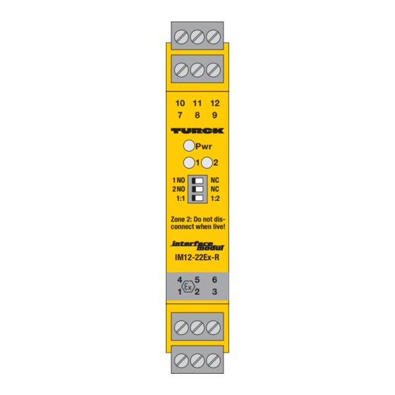
LED-Anzeigen (Fig. 1 + 2, Seite 2)
Pwr
grün
Betriebsbereitschaft
1, 2
kanalweise Zustandsanzeige:
gelb
Relais erregt
aus
Relais entregt
Klemmenbelegung (Fig. 1 + 2, Seite 2)
1, 4
eigensicherer Eingangskreis Kanal 1
2, 5
eigensicherer Eingangskreis Kanal 2
7, 10
Ausgangskreis Kanal 1
8, 9
Ausgangskreis Kanal 2
11,12
Betriebsspannungsanschluss gemäß
seitlicher Gehäusebedruckung
Anschluss durch Flachklemmen mit selbstab-
hebenden Andruckscheiben, Anschlussquer-
schnitt ≤ 1 × 2,5 mm², 2 × 1,5 mm² oder
2 × 1,0 mm
2
mit Ader-Endhülsen.
Funktionstabelle
Aufgeführt sind die verschiedenen Eingangs-
zustände mit den entsprechenden Ausgangs-
zuständen. Zu beachten ist, dass in der Regel
das Schaltverhalten von induktiven Sensoren
nach EN 60947-5-6 (NAMUR) dem von me-
chanischen Öffner-Kontakten entspricht. Das
Schaltverhalten von kapazitiven und magnet-
induktiven Sensoren entspricht dem von Schlie-
ßer-Kontakten entspricht.
Eingang/input/circuit de commande
Induktiver Sensor
mechanischer Kontakt
inductive sensor
dry contact
détecteur inductif
contact mécanique
EN 60947-5-6
(NAMUR)
Isolation switching amplifi ers
IM12-22Ex-R
Short description
• Galvanically isolated transmission of binary
switching signals
• Intrinsically safe input circuits Ex ia for
sensors according to EN 60947-5-6 (NAMUR)
or mechanical switches, which may be
located in explosion hazardous areas
• Area of application acc. to ATEX:
II (1) GD, II 3 G
• Approved for installation in zone 2
• 2-channel device
• Separately adjustable output performance
of each channel
• Removable terminal blocks
• Output circuits: one N.O. contact per output
• Without input circuit monitoring
• Adjustable signal multiplication
LED indications (Fig. 1 + 2, page 2)
Pwr
green
power on
1, 2
channel status:
yellow
relay energised
off
relay de-energised
Terminal confi guration (Fig. 1 + 2, page 2)
1, 4
intrinsically safe input circuit channel 1
2, 5
intrinsically safe input circuit channel 2
7, 10
output circuit channel 1
8, 9
output circuit channel 2
11,12
supply voltage connection according
to side imprint on housing
Connection via fl at terminals with self-lifting
pressure plates, connection profi le ≤ 1 × 2.5 mm²,
2
2 × 1.5 mm² or 2 × 1.0 mm
Function table
The various input states are listed together with
the according output states. Please note that
the switching performance of inductive sensors
per EN 60947-5-6 (NAMUR) usually accords
to that of mechanical normally closed contacts,
while the switching performance of capacitive
and magnet-inductive sensor accords to that of
normally open contacts.
Wirkungsrichtung
Ausgang/output/sortie
Function mode
Sens d'action
Schaltausgang
switching output
sortie de commutation
Arbeitsstromverhalten
normally open mode
fonction travail
NO
Amplifi cateurs séparateurs
IM12-22Ex-R
Description brève
• Transmission des états de commutation
binaires séparée galvaniquement
• Circuits d'entrée à sécurité intrinsèque Ex ia
pour le raccordement de détecteurs suivant
EN 60947-5-6 (NAMUR) ou de commutateurs
mécaniques pouvant se trouver dans la zone
Ex
• Champ d'application suivant ATEX:
II (1) GD, II 3 G
• Certifi é pour montage en zone 2
• Appareil à deux canaux
• Sens d'action programmable par canal
• Borniers débrochables
• Circuits de sortie: Un contact N.0.par sortie
• Pas de surveillance du circuit d'entrée
• Multiplication de signaux programmable
Visualisations par LED (Fig. 1 + 2, page 2)
Pwr
1, 2
Raccordement des bornes (Fig. 1 + 2, page 2)
1, 4
2, 5
7, 10
8, 9
11,12
Raccordement par cosses planes avec rondelles
à poussoir à dégagement automatique, section
raccordable ≤ 1 × 2,5 mm², 2 × 1,5 mm² ou
with wire sleeves.
2 × 1,0 mm
Tableau fonctionnel
Le tableau montre les différents états d'entrée
avec les états de sortie correspondants. Il est à
respecter que le comportement de commuta-
tion des détecteurs inductifs suivant
EN 60947-5-6 (NAMUR) correspond à celui
des contacts N.C. et que le comportement des
détecteurs capacitifs et magnéto-inductifs à
celui des contacts N.O.
Wirkungsrichtung
Function mode
Sens d'action
Ruhestromverhalten
normally closed mode
0
fonction repos
NC
1
verte
tension de service
visualisation de l'état par canal:
jaune
relais excité
off
relais désexcité
circ. d'entrée à sécurité intrin. canal 1
circ. d'entrée à sécurité intrin. canal 2
circuit de sortie canal 1
circuit de sortie canal 2
raccordement de la tension de service
suivant l'impression latérale sur l'appareil
2
avec cosses.
Ausgang/output/sortie
Schaltausgang
switching output
sortie de commutation
1
0
Advertisement

Related Manuals for turck IM12-22Ex-R


Summary of Contents for turck IM12-22Ex-R
- Page 1 Trennschaltverstärker Isolation switching amplifi ers Amplifi cateurs séparateurs IM12-22Ex-R IM12-22Ex-R IM12-22Ex-R Gerätekurzbeschreibung Short description Description brève • Galvanisch getrennte Übertragung von • Galvanically isolated transmission of binary • Transmission des états de commutation binären Schaltzuständen switching signals binaires séparée galvaniquement •...
- Page 2 IM12-22Ex-R Funktionseinstellung (Fig. 1) Function adjustment (Fig. 1) Programmation de la fonction (Fig. 1) Mit den drei frontseitigen Schaltern lassen sich Three front panel switches serve to adjust the Les trois commutateurs en face frontale per- für den Kanal 1 und 2 die Wirkungsrichtung des...
- Page 3 fi gurent au verso. L‘ensemble des certifi cats nationaux et Geräte fi nden Sie im Internet (www.turck.com). tional approvals covering Turck devices are obtainable via the internationaux des appareils TURCK peuvent être obtenus Die Besonderen Bedingungen IECEx CoC sind unter Internet (www.turck.com).
- Page 4 Name and signature of authorized person EN 60715-TH35 ø 4,5 Irrtümer und Änderungen vorbehalten / Subject to change without notice / Sous réserve de modifi cations © Hans Turck GmbH & Co. KG 2011 • Hans Turck GmbH & Co. KG Witzlebenstraße 7 45472 Mülheim/Ruhr...
Need help?
Do you have a question about the IM12-22Ex-R and is the answer not in the manual?
Questions and answers