Advertisement
Quick Links
Total solder points: 224
Difficulty level:
beginner 1o 2o 3þ 4o 5oadvanced
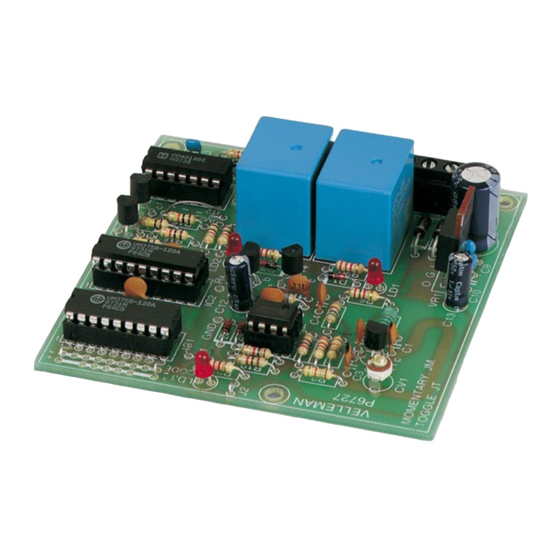
Two channel codelock receiver
Features:
þ Easy to build: no coils to be made!
þ Works together with the K6706/K6706A two channel transmitter.
þ For operating garage door.
þ Operating outdoor or indoor lights.
þ Remote control of electrical door locks.
þ Remote control of pool lights or fountain...
þ Two power relays included.
þ Each output selectable for toggle or pulse contact.
þ It is possible to put two receivers in cascade at same location, for
four channel output (in combination with two transmitters).
Specifications :
Two code channels.
•
8.748 possible codes.
•
On / off LED indication for each channel.
•
Two 10A relay outputs.
•
Dimensions: 85 x 85mm
•
Power supply: 2x9VAC or 12 to 16VDC / 120mA
•
* modifications reserved.
NOT SUITED TO OPERATE MACHINES OR OTHER
!
EQUIPMENT THAT COULD CAUSE INJURIES.
ILLUSTRATED ASSEMBLY MANUAL
K6727
H6727IP-2
Advertisement

Related Manuals for Velleman-Kit K6727


Summary of Contents for Velleman-Kit K6727
- Page 1 Total solder points: 224 Difficulty level: beginner 1o 2o 3þ 4o 5oadvanced Two channel codelock receiver K6727 Features: þ Easy to build: no coils to be made! þ Works together with the K6706/K6706A two channel transmitter. þ For operating garage door.
- Page 2 VELLEMAN Components NV Legen Heirweg 33 9890 Gavere Belgium Europe www.velleman.be www.velleman-kit.com...
- Page 3 Assembly hints 1. Assembly (Skipping this can lead to troubles ! ) Ok, so we have your attention. These hints will help you to make this project success- ful. Read them carefully. 1.1 Make sure you have the right tools: A good quality soldering iron (25- •...
- Page 4 MOUNTING SEQUENCE ! REMOVE THEM FROM THE TAPE ONE AT A TIME ! Velleman hereby certifies that the device K6727 meets the essential requirements and all other relevant stipulations of directive 1999/5/EG and 1995/5/EC. For the complete conformity declaration check out :...
- Page 5 C O L O R = 2 … 5 COLOR= 2...5 4K7= ( 4 - 7 - 2 - B ) 4K7= ( 4 - 7 - 0 - 1 - 1 ) CODICE CODIGO CODIGO VÄRI FÄRG FARVE- FARGE- FARB COLOUR CODIFI-...
- Page 6 Construction 4. SAW resonator 1. Jumper wires (check the position of the notch) L... q J1 q L1 : 1µH (1-0-B) q J2 5. 1/4W Resistors 2. Diodes R... Watch the polarity ! D... CATHODE q R1: 270 (2-7-1-B) q R2: 18K (1-8-3-B) q R3: 18K (1-8-3-B)
- Page 7 Construction IC sockets. q C5: 330p (331) q C6: 330p (331) (check the position of the notch) q C7: 330p (331) q C8: 330p (331) q C9: 100n (104) IC... q C10: 100n (104) q C11: 100n (104) q IC1 : 18p q IC2 : 18p 9.
- Page 8 Construction 11. Screw connectors 14. Relays First slide the connectors together one by one. RY... q RY1 : VR15 q RY2 : VR15 q SK1: 3-POLE q SK2: 3-POLE 15. ICs q SK3: 3-POLE (check the position of the notch) 12.
- Page 9 Personal code 16. Create your code You can select your own code for a transmitter/receiver combi- nation. There is a 9 row jumper island located directly next to IC1 for setting the code. The code is set by connecting one or more code points to a neighboring ‘+’...
-
Page 10: Operating Mode
Operating mode 17. Sticker Velleman Affix the supplied sticker to the housing. 433,92 MHz SRFCE 18. Operating mode By using the jumpers JM1 or JT1, channel 1 of the receiver can be set up for two output possibilities: 1. Output channel 1 is on while the transmitter is pressed (MOMENT), this is mostly used for operating a door lock, garage door, etc. - Page 11 Test & set-up 19. Test and set-up IMPORTANT: For adjusting the receiver, a completely plastic tuning • screwdriver (including plastic blade) is needed. This is sup- plied with the receiver. The transmitter must be in its housing with the cover on, •...
- Page 12 For more precise tuning, activate the transmitter from a • few meters away and then fine-tune the transmitter. REMARK: When a new receiver K6727 is used in con- junction with a one channel receiver K6707, then on the K6707 capacitor C1 must be a 1pF type.
- Page 13 COM1 OUTPUT OUTPUT TRANSFO 9VAC MAINS 12...16VDC K6727 K6727 9VAC Other connections: When using the relay output there is a choice between a nor- mally closed contact (NC) or a normally open contact (NO). The common output is at COM.
-
Page 14: Pcb Layout
PCB layout. - Page 16 Modifications and typographical errors reserved © Velleman Components nv. H6727IP - 2002 - ED2...
Need help?
Do you have a question about the K6727 and is the answer not in the manual?
Questions and answers