Advertisement
Quick Links
Advertisement

Related Manuals for BCP SKY6138


Summary of Contents for BCP SKY6138
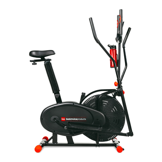
- Page 1 INSTRUCTION MANUAL Elliptical Bike SKY6138 Ver. 3...
- Page 2 NOTICE Please retain these instructions for future reference. • Keep children and pets away from this machine at all times. • Reconfirm that all bolts, screws, and knobs are secure every 90 days. May vary depending on how often you use this item. •...
- Page 3 TOOLS REQUIRED (PROVIDED) AAA - S8 ALLEN WRENCH 2 AAA BATTERIES SCREWDRIVER MULTITOOL 220 LBS 1 PERSON UP TO 60 MIN. CAPACITY ASSEMBLY ASSEMBLY S6 ALLEN WRENCH SPANNER MULTITOOL HARDWARE M10 X 57mm PEDAL HING S13 NUT CAP S18 NUT CAP BOLT SET BOLT SET (L/R) 4 PCS...
- Page 4 PARTS MAIN FRAME FRONT REAR LEFT FRAME STABILIZER STABILIZER WITH WHEEL 1 PC 1 PC 1 PC 1 PC RIGHT FRAME LEFT PEDAL RIGHT PEDAL SEAT 1 PC 1 PC 1 PC 1 PC DECORATIVE LEFT HANDLE SADDLE SADDLE POST SLEEVE ADJUSTMENT 1 PC...
- Page 5 PRODUCT ASSEMBLY Locate the part B front stabilizer and attach it to the front of the part A main frame with two part 1 bolt sets. Repeat to attach the part C rear stabilizer. NOTE: The front stabilizer has a set of wheels for moving your elliptical bike. Locate the part 5 handlebar shaft, remove the hardware and set aside.
- Page 6 PRODUCT ASSEMBLY Slide the part D and E frame bars onto the handlebar shaft and secure with the remaining bolt and washer sets removed in the previous step. NOTE: Use two allen wrenches to tighten both ends of the handlebar shaft at the same time. Tighten one side clockwise and the other counterclockwise.
- Page 7 PRODUCT ASSEMBLY Attach the part F and G pedals with four part 8 bolts and nut sets. Attach the four part 7 end caps as indicated. Insert the part L left handlebar into the part D left frame bar. Select a comfortable height and secure with the adjustment knob.
- Page 8 PRODUCT ASSEMBLY Connect the wires on the main frame and the part N computer post, then insert the computer post into the main frame and secure with two part 9 adjustment knobs. Remove the two screws from the part N computer post, then use the screws to attach the part P bottle holder to the part N computer post.
- Page 9 PRODUCT ASSEMBLY Locate the part O computer and connect the corresponding wires. Remove four screws from the back of the computer, then use the screws to secure the computer to the bracket. Insert (2) AAA batteries into the computer.
- Page 10 PRODUCT ASSEMBLY Remove the adjustment bolt and washer from the part I adjustment bar. Place the washer on the part J saddle post, then slide the adjustment bar into the saddle post and secure with the previously removed adjustment bolt. Locate the part H seat and remove the three nylon nuts and washers on the bottom.
- Page 11 TENSION ADJUSTMENT • Before beginning your first workout, adjust the tension to a manageable level. • When starting your exercise, simply use the tension adjustment knob (found at the top center) to manipulate the resistance you feel. • Turn the knob clockwise to increase the tension, turn the knob counter-clockwise to lower the tension. DISPLAY RANGES Time 00:00-99:59...
-
Page 12: Help Center
HELP CENTER Question about your product? We're here to help. Visit us at: help.bestchoiceproducts.com CHAT Chat Support Product Inquiry Orders FAQ Product Assembly Returns & Refunds PRODUCT WARRANTY INFORMATION All items can be returned for any reason within 60 days of the receipt and will receive a full refund as long as the item is returned in its original product packaging and all accessories from its original shipment are included.
Need help?
Do you have a question about the SKY6138 and is the answer not in the manual?
Questions and answers