Endress+Hauser Prosonic M FMU40 Operating Instructions Manual
Ultrasonic level measurement
Hide thumbs
Also See for Prosonic M FMU40:
- Operating instructions manual (112 pages) ,
- Technical information (52 pages) ,
- Brief operating instructions (36 pages)

Related Manuals for Endress+Hauser Prosonic M FMU40


Summary of Contents for Endress+Hauser Prosonic M FMU40
- Page 1 Operating Instructions Prosonic M FMU40/41/42/43 Ultrasonic Level Measurement BA239F/00/en/04.05 52010988 Valid as of software version: V 01.02.00 (amplifier) V 1.0 (communication)
- Page 2 Short instructions Prosonic M FMU 40/41/42/43 with Foundation Fieldbus Short instructions KA 183F/00/a2/02.02 Prosonic M - Quick Setup 52010993 Contrast: measured value dist./ meas value Group selection basic setup tank shape medium process empty blocking full dist./ check range of start property cond.
-
Page 3: Table Of Contents
Product structure FMU 41 ....8 8.10 Contact addresses of Endress+Hauser ... 68 Product structure FMU 42 . -
Page 4: Safety Instructions
Safety instructions Prosonic M FMU 40/41/42/43 with Foundation Fieldbus Safety instructions Designated use The Prosonic M is a compact measuring device for continuous, non-contact level measurement. Depending on the sensor, the measuring range is up to 15m in fluids and up to 7m in bulk solids. By using the linearisation function, the Prosonic M can also be used for flow measurements in open channels and measuring weirs. -
Page 5: Notes On Safety Conventions And Symbols
Prosonic M FMU 40/41/42/43 with Foundation Fieldbus Safety instructions Notes on safety conventions and symbols In order to highlight safety-relevant or alternative operating procedures in the manual, the following conventions have been used, each indicated by a corresponding symbol in the margin. Safety conventions Warning! A warning highlights actions or procedures which, if not performed correctly, will lead to personal... -
Page 6: Identification
Identification Prosonic M FMU 40/41/42/43 with Foundation Fieldbus Identification Nameplate ENDRESS+HAUSER Made in Germany PROSONIC-M D-79689 Maulburg Order Code: Ser.-No.: IP68 / NEMA 6P Profibus PA Foundation Fieldbus 90 … 253 V AC 4VA 10,5 …32 V DC 1W 14 … 36 V DC 0,8W 4 …... -
Page 7: Product Structure Fmu 40
Prosonic M FMU 40/41/42/43 with Foundation Fieldbus Identification Product structure FMU 40 Certificates A Variant for non-hazardous area ATEX II 1/2 G or II 2 G; EEX ia IIC T6 ATEX II 1/2 G or II 2 G; EEX d [ia] IIC T6 G ATEX II 3G EEx nA II T6 ATEX II 1/2D, Alu blind cover ATEX II 1/3D... -
Page 8: Product Structure Fmu 41
Identification Prosonic M FMU 40/41/42/43 with Foundation Fieldbus Product structure FMU 41 Certificates A Variant for non-hazardous area ATEX II 1/2 G or II 2 G; EEX ia IIC T6 ATEX II 1/2 G or II 2 G; EEX d [ia] IIC T6 G ATEX II 3G EEx nA II T6 ATEX II 1/2D, Alu blind cover ATEX II 1/3D... -
Page 9: Product Structure Fmu 42
Prosonic M FMU 40/41/42/43 with Foundation Fieldbus Identification Product structure FMU 42 Certificates A Variant for non-hazardous area ATEX II 1/2 G EEX ia IIC T6 ATEX II 1/2 G EEX d [ia] IIC T6 G ATEX II 3G EEx nA II T6 (in preparation) FM IS Cl. -
Page 10: Product Structure Fmu 43
Identification Prosonic M FMU 40/41/42/43 with Foundation Fieldbus Product structure FMU 43 Certificates A Variant for non-hazardous area ATEX II 1/2 D or II 2 D, Aluminium Deckel ATEX II 1/3 D or II 3 D, Sichtdeckel M FM DIP Class II, III, Div. 1, Gr. E,F,G NI N CSA General Purpose CSA DIP, Class II, III, Div. -
Page 11: Scope Of Delivery
The device complies with the applicable standards and regulations as listed in the EC declaration of conformity and thus complies with the statutory requirements of the EG directives. Endress+Hauser confirms the successful testing of the device by affixing to it the CE mark. -
Page 12: Installation
Installation Prosonic M FMU 40/41/42/43 with Foundation Fieldbus Installation Dimensions F12 housing T12 housing ca. 86 ENDRESS+HAUSER ENDRESS+HAUSER Prosonic M Prosonic M FMU 42 with universal flange FMU 40 FMU 41 60 AF 60 AF Flange: DN80/ANSI3"/JIS10K80 G1½” DN100/ANSI4"/JIS16K100 G2”... -
Page 13: Installation Variants
Sealing ring (EPDM) supplied counter nut (PC) supplied for G 1½” and G 2” instruments Installation with installation bracket Installation with adapter flange ENDRESS+HAUSER Prosonic M Sealing ring (EPDM) adapter flange supplied sensor nozzle L00-FMU4xxxx-17-00-00-en-002 For installation bracket or adapter flange s. chapter "Accessories". - Page 14 Installation Prosonic M FMU 40/41/42/43 with Foundation Fieldbus 3.2.2 Installation variants FMU 42 Installation with mounting bracket Installation with universal flange Flange: DN80/ANSI3"/JIS10K80 DN100/ANSI4"/JIS16K100 L00-FMU42xxxx-17-00-00-en-001 3.2.3 Installation variants FMU 43 Installation with Installation with universal slip-on flange (option) mounting bracket slip-on flange sensor nozzle...
-
Page 15: Installation Conditions
10 m 0,96 m FMU 43 6° 15 m 0,79 m 3.3.2 Installation in narrow shafts In narrow shafts with strong interference ENDRESS+HAUSER ENDRESS+HAUSER ENDRESS+HAUSER ENDRESS+HAUSER Prosonic M Prosonic M Prosonic M Prosonic M echoes, we recommend using an ultrasound guide pipe (e.g. - Page 16 Installation Prosonic M FMU 40/41/42/43 with Foundation Fieldbus 3.3.3 Installation conditions for flow measurements • Install the Prosonic M at the inflow side, as close above the maximum water level H as possible (take into account the blocking distance BD). •...
- Page 17 Prosonic M FMU 40/41/42/43 with Foundation Fieldbus Installation Example: Triangular weir min. 2 H α (= full calibr.) min. 2 H min. 3 H L00-FMU4xxxx-17-00-00-en-012...
-
Page 18: Measuring Range
Installation Prosonic M FMU 40/41/42/43 with Foundation Fieldbus Measuring range 3.4.1 Blocking distance, Nozzle mounting Install the Prosonic M at a height so that the blocking distance BD is not undershot, even at maximum fill level. Use a pipe nozzle if you cannot maintain the blocking distance in any other way. The interior of the nozzle must be smooth and may not contain any edges or welded joints. - Page 19 Prosonic M FMU 40/41/42/43 with Foundation Fieldbus Installation 3.4.2 Safety distance If the level rises to the safety distance SD, the device switches to warning or alarm status. The size of SD can be set freely in the "Safety distance" (015) function.The "in safety distance" (016) function defines how the device reacts if the level enters the safety distance.
-
Page 20: Installation Hint For Fmu 40/41
Installation Prosonic M FMU 40/41/42/43 with Foundation Fieldbus Installation hint for FMU 40/41 Screw the Prosonic M at the screw-in piece F12 or T12 housing using an 60 AF spanner. Maximum torque: 20 Nm. Caution! Use only the screw-in piece to screw in the Prosonic M AF 60 max torque... -
Page 21: Wiring
Prosonic M FMU 40/41/42/43 with Foundation Fieldbus Wiring Wiring Electrical connection " Caution! Before connection please note the following: • The power supply must be identical to the data on the nameplate. • Switch off power supply before connecting up the instrument. •... - Page 22 Wiring Prosonic M FMU 40/41/42/43 with Foundation Fieldbus 4.1.2 Wiring in the housing T12 Unscrew the cover (1) of the separate connection room. Insert cable (2) through gland (3). " Caution! If possible, insert the cable from above and let a draining loop in order to avoid intrusion of humidity.
-
Page 23: Terminal Assignment
Prosonic M FMU 40/41/42/43 with Foundation Fieldbus Wiring Terminal assignment plant ground – L00-FMxxxxxx-04-00-00-en-013 Cable specifications Foundation Fieldbus Twisted, shielded pairs must be used. The cable specifications can be taken from the FF specification or IEC 61158-2. The following have been found suitable: Non-Ex-area: •... -
Page 24: Recommended Connection
Wiring Prosonic M FMU 40/41/42/43 with Foundation Fieldbus Recommended connection L00-FMU4xxxx-17-00-00-yy-014 1: external ground terminal of the transmitter For maximum EMC protection please observe the following points: • As the metal housing of the Prosonic M is isolated from the tank by the plastic sensor, a low- impedance connection between the housing and tank/bracket/flange should be installed in order to ensure electromagnetic compatibility (EMC). -
Page 25: Operation
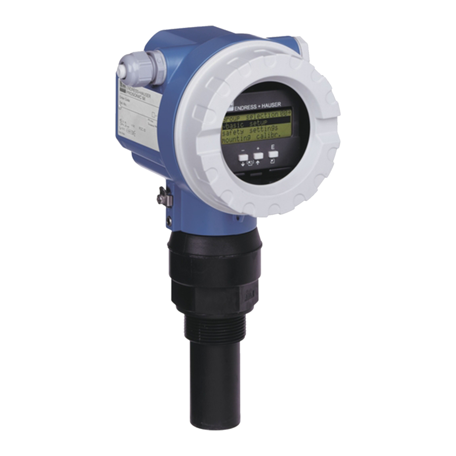
Prosonic M FMU 40/41/42/43 with Foundation Fieldbus Operation Operation Display and operating elements 5.1.1 On-site display VU 331 The LCD module VU 331 for display and operation is located beneath the housing cover. The measured value is legible through the glass in the cover. Open the cover to operate the device. (liquid crystal display) Orde Ser.-... - Page 26 Operation Prosonic M FMU 40/41/42/43 with Foundation Fieldbus 5.1.2 Display appearance position in menu label measured value display symbol value bargraph unit group selection selection list position in menu label function with free parameter help texts envelope curve envelope curve display L00-FMxxxxxx-07-00-00-en-002 In the measured value display, the bargraph corresponds to the output.
-
Page 27: Function Codes
Prosonic M FMU 40/41/42/43 with Foundation Fieldbus Operation 5.1.4 Function of the keys Key(s) Meaning Navigate upwards in the selection list Edit numeric value within a function Navigate downwards in the selection list Edit numeric value within a function Navigate to the left within a function group Navigate to the right within a function group, confirmation. -
Page 28: Foundation Fieldbus Interface
Operation Prosonic M FMU 40/41/42/43 with Foundation Fieldbus Foundation Fieldbus interface 5.3.1 Synopsis There are two possibilities of connecting up a Foundation Fieldbus: Direct connection to a FF/H1 card Controller H1 interface Analog input Analog output Digital input FF/H1 Field devices (e.g. Micropilot M, Levelflex M, Prosonic M) L00-FMR2xxxx-14-00-06-en-025 Indirect connection via a linking device... - Page 29 Prosonic M FMU 40/41/42/43 with Foundation Fieldbus Operation 5.3.2 Hardware settings A DIP-switch in the connection compartment of the instrument allows the write protection and simulation functions to be set via hardware. • If "SIM" is switched off, the simulation function is not accesible in the configuration tool. •...
- Page 30 • When the configuration is complete, close the tool and the FF stack (if open). The Prosonic M device descriptions can be ordered direct from Endress+Hauser or downloaded from our website www.endress.com. They contain all data necessary to operate Endress+Hauser Foundation Fieldbus devices.
- Page 31 Prosonic M FMU 40/41/42/43 with Foundation Fieldbus Operation 5.3.4 Block model of the Prosonic M The Prosonic M contains the follwoing blocks: • Resource Block (RB2) s. Operating Instructions BA 013S: "Foundation Fieldbus - Overview" • Transducer Block (TB) contains the parameters relevant to the measurement •...
- Page 32 Operation Prosonic M FMU 40/41/42/43 with Foundation Fieldbus 5.3.5 Resource Block E+H_PROSONIC_M_XXXXXXXX RESOURCE_XXXXXX (RB2) TRANSDUCER_XXXXXX (TBUL) ANALOG_INPUT_1_XXXXXX (AI) Operation The resource block contains the parameters used to describe physical resources of the device. It has no linkable inputs or outputs. The resource block is opened by a click on the resource line.
- Page 33 Prosonic M FMU 40/41/42/43 with Foundation Fieldbus Operation 5.3.6 Transducer Block E+H_PROSONIC_M_XXXXXXXX RESOURCE_XXXXXX (RB2) TRANSDUCER_XXXXXX (TBUL) ANALOG_INPUT_1_XXXXXX (AI) Operation The transducer block contains the parameters required to calibrate the device. These parameters can also be addressed by using the VU 331 display module. The transducer block is opened by clicking on the transducer line.
- Page 34 Operation Prosonic M FMU 40/41/42/43 with Foundation Fieldbus Methods The Foundation Fieldbus specification provides for the use of so-called methods to simplify the operation of the device. A method is an interactive sequence of steps that must be followed in order to obtain a particular function from the device.
- Page 35 Prosonic M FMU 40/41/42/43 with Foundation Fieldbus Operation Profile code of Transducer Block The current profile code of the Prosonic M Transducer Block is 0x8010 Parameter list of the Prosonic M Transducer Block Parameter Position rel. Variable Name Size Type Read Write Storage...
- Page 36 Operation Prosonic M FMU 40/41/42/43 with Foundation Fieldbus Parameter Position rel. Variable Name Size Type Read Write Storage Indicator Index [bytes] Class outp. echo loss PARREACTIONLOSTECHO UNSIGNED8 static ramp %span/min PARRAMPINPERCENTPERMIN FLOAT static delay time PARDELAYTIMEONLOSTECHO UNSIGNED16 static safety distance PARLEVELWITHINSAFETYDISTANCE FLOAT static...
- Page 37 Prosonic M FMU 40/41/42/43 with Foundation Fieldbus Operation 5.3.7 Analog input block E+H_MICROPILOT_M_XXXXXXXX RESOURCE_XXXXXX (RB2) TRANSDUCER_XXXXXX (TBRL) ANALOG_INPUT_1_XXXXXX (AI) The analog input block condito ns the signal output by the transducer block andoutputs signal to the PCL or other function blocks. L00-FMR2xxxx-05-00-00-en-008 Operation The resource block is opened by a click on the resource line.
- Page 38 Operation Prosonic M FMU 40/41/42/43 with Foundation Fieldbus Output values Parameter Description Either the primary/secondary transducer block value used to execute the block or a pro- cess value associated with it. Comprises value and status. The primary value output as a result of executing the analog input block. Comprises value and status.
- Page 39 Prosonic M FMU 40/41/42/43 with Foundation Fieldbus Operation Output response parameters Parameter Description LOW_CUT Not relevant to level measurement! Determines a threshold for square root linearization below which the output value is set to zero. PV_FTIME Sets the time constant for the output value. Alarm parameters Parameter Description...
- Page 40 Operation Prosonic M FMU 40/41/42/43 with Foundation Fieldbus Simulation The SIMULATE parameter allows the transducer block output value to be simulated, provided simulation has also been enabled at the device DIP switch. The simulation must be enabled, a value and/or status entered and the block must be in AUTO mode. During simulation the transducer output value is substituted by the simulated value.
- Page 41 Prosonic M FMU 40/41/42/43 with Foundation Fieldbus Operation Object Start Index Resource Block Analog Input 1 Function Block Analog Input 2 Function Block PID Function Block Arithmetic Function Block Input Selector Function Block Signal Characterizer Function Block Integrator Function Block Transducer Block Object Start Index...
- Page 42 5.3.10 Parameter access via ToF Tool The ToF Tool is a graphical operation software for instruments from Endress+Hauser. It is used to support commissioning, securing of data, signal analysis and documentation of the instruments. It is compatible with the following operating systems: WinNT4.0, Win2000 and WinXP.
- Page 43 Prosonic M FMU 40/41/42/43 with Foundation Fieldbus Operation L00-FMU4xxxx-19-00-00-en-004 Connection • Service-Interface with adapter FXA 193...
-
Page 44: Operation Using The On-Site Display Vu 331
Operation Prosonic M FMU 40/41/42/43 with Foundation Fieldbus Operation using the on-site display VU 331 ENDRESS + HAUSER – >3 s Return to basic setup medium property tank shape Group Selection unknown dome ceiling safety settings liquid horizontal cyl temperature solid<4mm bypass solid>4mm... -
Page 45: Lock/Unlock Configuration
Prosonic M FMU 40/41/42/43 with Foundation Fieldbus Operation Lock/unlock configuration 5.5.1 Software security locking Enter a number ≠ 2457 in the "unlock parameter" (0A4) function in the "diagnostics" (0A) function group. symbol appears on the display. Inputs are no longer possible. If you try to change a parameter, the device jumps to the "unlock parameter"... -
Page 46: Resetting An Interference Echo Suppression (Tank Map)
Operation Prosonic M FMU 40/41/42/43 with Foundation Fieldbus Resetting an interference echo suppression (tank map) It is always advisable to reset the interference echo suppression (tank mapping) when: • a device with an unknown history is used • an incorrect suppression was input. Proceed as follows: Switch to the "extended calibr."... -
Page 47: Commissioning
Prosonic M FMU 40/41/42/43 with Foundation Fieldbus Commissioning Commissioning Commission the Prosonic M in the following stages: • Installation check • Power-up device • Basic calibration • Measuring signal check using the envelope curve The chapter describes the commissioning process using the on-site display. Commissioning using ToF Tool is identical. -
Page 48: Basic Calibration
Measuring point settings Function "tank shape" (002) In this function, select one of the following options: dome ceiling horizontal cyl bypass stilling well ENDRESS+HAUSER Prosonic M (ultrasonic guide pipe) no ceiling sphere flat ceiling e.g. dumps, open levels chanels, weirs L00-FMU4xxxx-14-00-06-en-001 Function "medium property"... - Page 49 Prosonic M FMU 40/41/42/43 with Foundation Fieldbus Commissioning Function "process conditions" (004) For this function, you have the following options: standard liquids calm surface turb. surface For all fluid applications which do not Storage tanks with immersion tube or Storage / accumulation tanks with fit in any of the following groups.
- Page 50 Test: no filter Dusty bulk solids Bulk solids with rapid level change All the filters can be switched off for purposes of service and diagnosis. ENDRESS+HAUSER Prosonic M L00-FMU4xxxx-14-00-00-xx-007 L00-FMU4xxxx-14-00-00-xx-005 The filters are set to detect even The averaging filters are set to small All filters off relatively weak signals.
- Page 51 Prosonic M FMU 40/41/42/43 with Foundation Fieldbus Commissioning 6.2.2 Empty and full calibration 20 mA 100% 4 mA L00-FMU4xxxx-19-00-00-yy-019 Function "empty calibration" (005) In this function, enter the distance E from the sensor membrane to the minimum level (zero point). "...
- Page 52 Commissioning Prosonic M FMU 40/41/42/43 with Foundation Fieldbus 6.2.3 Interference echo suppression (tank mapping) Function "dist./measured value" (008) In the "dist./meas.value" (008) function, the measured distance D from the sensor membrane to the product surface is displayed together with level L. Check these values. Function "check distance"...
- Page 53 Prosonic M FMU 40/41/42/43 with Foundation Fieldbus Commissioning Function "start mapping" (053) You have the following options for this function: • off: Nothing is suppressed. • on: Starts suppression. Note! If a mapping already exists, it will be overwritten up to the distance specified in the "range of mapping"...
-
Page 54: Envelope Curve
Commissioning Prosonic M FMU 40/41/42/43 with Foundation Fieldbus Envelope curve After the basic setup, an evaluation of the measurement with the aid of the envelope curve ("envelope curve" (0E) function group) is recommended. 6.3.1 Funxtion "plot settings" (0E1) In this function, select whether you want to display •... - Page 55 Prosonic M FMU 40/41/42/43 with Foundation Fieldbus Commissioning 6.3.4 Navigation in the envelope curve display Using navigation, the envelope curve can be scaled horizontally and vertically and shifted to the left or the right. The active navigation mode is indicated by a symbol in the top left hand corner of the display.
- Page 56 Commissioning Prosonic M FMU 40/41/42/43 with Foundation Fieldbus Exiting the navigation • Press again to run through the different modes of the envelope curve navigation. • Press to exit the navigation. The set increases and shifts are retained. Only when you reactivate the "recording curve"...
-
Page 57: Troubleshooting
Prosonic M FMU 40/41/42/43 with Foundation Fieldbus Troubleshooting Troubleshooting System error messages 7.1.1 Current error Errors which the Prosonic M detects during commissioning or operation are displayed: • In the "measured value" (000) function • In the "diagnostics" (0A) function group in the "present error" (0A0) function Only the highest priority error is displayed;... - Page 58 Troubleshooting Prosonic M FMU 40/41/42/43 with Foundation Fieldbus Code Error description Action A281 interruption temperature Exchange sensor sensor A502 Sensor type not detected Exchange sensor and/or electronics A512 recording of mapping Alarm disappears after a few seconds A521 new sensor type detected Reset W601 linearisation curve not...
-
Page 59: Application Errors
Prosonic M FMU 40/41/42/43 with Foundation Fieldbus Troubleshooting Application errors Error Example Elimination Measured value (00) is 1. Check empty calibration (005) and incorrect but measured full calibration (006). distance (008) is correct 100% F m/ft 2. Check linearisation – level/ullage (040) –... - Page 60 Troubleshooting Prosonic M FMU 40/41/42/43 with Foundation Fieldbus Error Example Elimination E 641 (echo loss) 1. Check application parameters (002), (003) and (004) 2. If necessary, select a different installation position and/or a larger sensor 100% 3. Align the sensor parallel to the product surface (particularly for bulk solids applications) eingetreten E 641...
-
Page 61: Maintenance And Repairs
Spare parts are contained in suitable kits. They contain the related replacement instructions. All the spare parts kits which you can order from Endress+Hauser for repairs are listed with their order numbers in the section "Spare parts". -
Page 62: Spare Parts (Housing Type F12)
Maintenance and repairs Prosonic M FMU 40/41/42/43 with Foundation Fieldbus Spare parts (housing type F12) O r d d e : r. - N o .: s s b e r e i n a a s u ic h r in g r a n 6 .. - Page 63 Prosonic M FMU 40/41/42/43 with Foundation Fieldbus Maintenance and repairs 10 Housing 543120-0022 Housing F12, aluminium, G1/2 543120-0023 Housing F12, aluminium, NPT1/2 543120-0024 Housing F12, aluminium, M20 52001992 Housing F12, aluminium, M20, PA connector 52008556 Housing F12, aluminium, M20, FF connector 52013350 Housing F12, aluminium, coated, M20, 4-wire 52013351 Housing F12, aluminium, coated, M20, metal 52013348 Housing F12, aluminium, coated, G1/2, 4-wire...
- Page 64 Maintenance and repairs Prosonic M FMU 40/41/42/43 with Foundation Fieldbus 55 Flanges 52023919 Flange, Uni-DN80/ANSI 3"/JIS 80A, PP 52023920 Flange, Uni-DN80/ANSI 3"/JIS 80A, PVDF 52023921 Flange, Uni-DN80/ANSI 3"/JIS 80A, 316L 52023922 Flange, Uni-DN100/ANSI 4"/JIS 100A, PP 52023923 Flange, Uni-DN100/ANSI 4"/JIS 100A, PVDF 58 Hexagon nut 52000599 Hexagon nut (SW60) G1-1/2, bk, PC 52000598 Hexagon nut (SW70) G2, bk, PC...
-
Page 65: Spare Parts (Housing Type T12)
Prosonic M FMU 40/41/42/43 with Foundation Fieldbus Maintenance and repairs Spare parts (housing type T12) O r d d e : r. - N o .: s s b e r e a s u ic h r in g r a n 6 .. - Page 66 Maintenance and repairs Prosonic M FMU 40/41/42/43 with Foundation Fieldbus 10 Housing 543180-1023 Housing T12, aluminium, NPT1/2, PEL 52006204 Housing T12, aluminium, G1/2, PEL, cover 52006205 Housing T12, aluminium, M20, PEL, cover 11 Hood for terminal compartment 52005643 Hood T12 12 Set of screws 535720-9020 Set of screws for housing F12/T12 20 Cover...
- Page 67 Prosonic M FMU 40/41/42/43 with Foundation Fieldbus Maintenance and repairs 58 Hexagon nut 52000598 Hexagon nut (SW70) G2, bk, PC 52000599 Hexagon nut (SW60) G1-1/2, bk, PC 65 Sealing kit 52010526 Sealing kit FMU4x Miscellaneous 52010545 Nameplate Prosonic M, modification...
-
Page 68: Return
Prosonic M FMU 40/41/42/43 with Foundation Fieldbus Return The following procedures must be carried out before a transmitter is sent to Endress+Hauser e.g. for repair or calibration: • Remove all residue which may be present. Pay special attention to the gasket grooves and crevices where fluid may be present. -
Page 69: Accessories
Prosonic M FMU 40/41/42/43 with Foundation Fieldbus Accessories Accessories Weather protection cover A Weather protection cover made of stainless steel is recommended for outdoor mounting (order code: 543199-0001). The shipment includes the protective cover and tension clamp. F12 / F23 / T12 housing M IC M IC O rd... -
Page 70: Adapter Flange For Fmu 40 / Fmu 41
Accessories Prosonic M FMU 40/41/42/43 with Foundation Fieldbus Adapter flange for FMU 40 / FMU 41 sealing ring adapter flange EPDM (supplied) sensor nozzle L00-FMUX3XXX-00-00-00-en-001 9.3.1 Version with metrical thread (FAU 70 E) Version 12 DN 50 PN 16 14 DN 80 PN 16 15 DN 100 PN 16 Thread G 1½, ISO 228... -
Page 71: Cantilever
Prosonic M FMU 40/41/42/43 with Foundation Fieldbus Accessories Cantilever L00-FMU4xxxx-06-00-00-yy-005 for Sensor Material Order Code 585 mm 250 mm 2 mm 200 mm FMU 40 1.4301 (AISI 304) 52014132 galv. steel 52014131 FMU 41 1.4301 (AISI 304) 52014136 galv. steel 52014135 1085 mm 750 mm... -
Page 72: Mounting Frame
Accessories Prosonic M FMU 40/41/42/43 with Foundation Fieldbus Mounting Frame 33.7 Ø L00-FMU4x-00-00-00-yy-005 Height Material Order Code 700 mm galv. steel 919791-0000 700 mm 1.4301 (AISI 304) 919791-0001 1400 mm galv. steel 919791-0002 1400 mm 1.4301 (AISI 304) 919791-0003 Wall Bracket ø... -
Page 73: Mounting Bracket For Fmu 43
Prosonic M FMU 40/41/42/43 with Foundation Fieldbus Accessories Mounting bracket for FMU 43 Material: 1.4301 Order-Code.: 942666-0000 L00-FMU4x-00-00-00-en-003.eps Service Interface FXA193 The Service-Interface connects the Service plug of Proline and ToF instruments with the 9 pin RS 232C interface of a PC. (USB connectors must be equipped with a usual commercial USB/Serial adapter.) 9.8.1 Product structure... -
Page 74: Remote Display Fhx40
Accessories Prosonic M FMU 40/41/42/43 with Foundation Fieldbus Remote display FHX40 Wall-mounting Pipe-mounting (without mounting bracket) (mounting bracket and plate supplied optionally, s. product structure) Separate housing FHX 40 (IP 65) Micropilot M Levelflex M Prosonic M O rd O rd d e : d e : r. -
Page 75: Technical Data
Prosonic M FMU 40/41/42/43 with Foundation Fieldbus Technical Data Technical Data 10.1 Technical data at a glance 10.1.1 Input Measured variable The distance D between the sensor membrane and the product surface is measured. Using the linearisation function, the device uses D to calculate: •... - Page 76 Technical Data Prosonic M FMU 40/41/42/43 with Foundation Fieldbus 10.1.4 Performance characteristics Reaction time The reaction time depends on the parameter settings (min. 2s). Reference operating • Temperature = +20 °C conditions • Pressure = 1013 mbar abs. • Humidity = 50 % •...
- Page 77 A temperature sensor is integrated in the sensor for correction of the temperature-dependent time- of-flight. Process pressure • FMU 40/41: 0.7 bar ... 3bar abs. • FMU 42/43: 0.7 bar ... 2.5bar abs. Note! For pressures less than 0.7 bar please contact Endress+Hauser...
-
Page 78: Appendix
Appendix Prosonic M FMU 40/41/42/43 with Foundation Fieldbus Appendix 11.1 Operating menu basic setup tank shape medium property process cond. empty calibr. full calibr. dome ceiling liquid standard liquid distance membrane span horizontal cyl. solid < 4mm calm surface to min. level max.: empty - BD bypass solid >... - Page 79 Prosonic M FMU 40/41/42/43 with Foundation Fieldbus Appendix dist./meas. value check distance range of mapping. start mapping dist./meas. value the following are manual accept proposed value the following are displayed: distance = ok displayed: - distance membrane distance too small specify range of - distance membrane to level...
-
Page 80: Measuring Principle
Appendix Prosonic M FMU 40/41/42/43 with Foundation Fieldbus 11.2 Measuring principle 20 mA 100% 4 mA L00-FMU4x-15-00-00-de-001 E: Empty distance; F: Span (full distance); D: Distance from sensor membrane - product surface; L: Level; BD: Blocking distance Sensor Max. range fluids Max. -
Page 81: Index
Prosonic M FMU 40/41/42/43 with Foundation Fieldbus Index Index adapter flange ........70 range. - Page 82 Prosonic M FMU 40/41/42/43 with Foundation Fieldbus Index...
- Page 83 Declaration of Contamination Erklärung zur Kontamination Because of legal regulations and for the safety of our employees and operating equipment, we need the "declaration of contamination", with your signature, before your order can be handled. Please make absolutely sure to include it with the shipping documents, or - even better - attach it to the outside of the packaging.
- Page 84 www.endress.com/worldwide BA239F/00/en/04.05 CCS/FM+SGML 6.0/ProMoDo 52010988...
Need help?
Do you have a question about the Prosonic M FMU40 and is the answer not in the manual?
Questions and answers