Table of Contents
Advertisement
Available languages
Available languages
Quick Links
Advertisement
Chapters
Table of Contents

Related Manuals for PCE Health and Fitness EV11


Summary of Contents for PCE Health and Fitness EV11
- Page 1 EV11 Montage- und Bedienungsanleitung Mounting and operating manual...
- Page 3 Montage- und Bedienungsanleitung WALLBOX EV11 Seite 4 - 21 Mounting and operating manual WALLBOX EV11 page 22 - 39...
-
Page 4: Table Of Contents
9.3 Ersatzteile ..................21 9.4 Kontakt zum Support ................ 21 9.5 Entsorgung ..................21 Dokument: 11202 EV11 BA V1.2 09/2021 © PC Electric Gesellschaft m.b.H. Dieses Dokument ist urheberrechtlich geschützt. Der Inhalt diese Dokumentes ist Eigentum der PC Electric Gesellschaft m.b.H. und darf weder ganz noch teilweise ohne Genehmigung des Rechtsinhabers vervielfältigt oder reproduziert werden. -
Page 5: Allgemeine Informationen
Einsatz nicht geprüfter Komponenten von gewährleisten den sicheren und effizienten Umgang Drittanbietern mit der WALLBOX EV11 für Mensch und Umwelt. Die Bedienungsanleitung ist ein Bestandteil des Produkts. Sie ist über die gesamte Lebensdauer des Produkts aufzubewahren und und muss vor Beginn aller Arbeiten sorgfältig vom Besitzer und allen Fach-... -
Page 6: Arten Der Sicherheitshinweise
Erläuterung Hinweis und Erfahrung sowie Kenntnis der einschlägigen Normen die übertragenen Arbeiten beurteilen und mögliche Gefahren Wichtige ergänzende Informationen zur PCE erkennen können. Wallbox EV11. 1.6 Sicherheitshinweise VORSICHT Möglicher Sachschaden! Das Ladekabel nur an der Ladekupplung und nicht am Kabel aus der Halterung ziehen. -
Page 7: Bestimmungsgemäße Verwendung
1.7 Bestimmungsgemäße 1.8 Vernünftigerweise vorher- Verwendung sehbare Fehlanwendung Die Ladestation ist für das Aufladen elektrisch be- Bei einer Verwendung außerhalb der vorgegebenen triebener Fahrzeuge, z.B. Elektrofahrzeuge (PEV) oder Grenzen oder bei einer Handhabung, die nicht in Plug-In-Hybrid Fahrzeuge (PHEV) bestimmt. dieser Bedienungsanleitung beschrieben ist, können die Sicherheit und die Eigenschaften des Produktes Die bestimmungsgemäße Verwendung der Ladesta-... -
Page 8: Beschreibung Der Ladestation
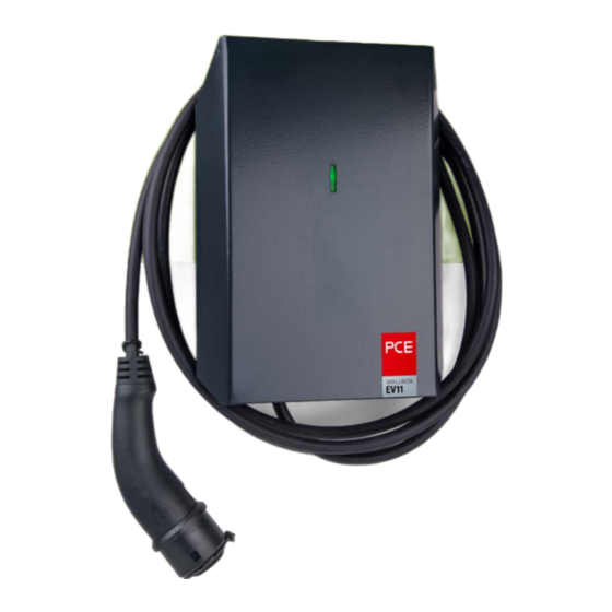
2. Beschreibung der Ladestation Kunststoffgehäuse: schlagfestes PC/ABS Gehäuseabdeckung und Montageplatte: Stahlblech, pulverbeschichtet RAL7016 LED Statusanzeige Ladekabel Fahrzeugkupplung Typ 2 Aufkleber LED Statusanzeige Typenetikett ACHTUNG! Fahrzeugsteckdose verriegelt während des Ladevorgangs. Der Ladevorgang muss unterbrochen werden um die Ladekupplung entfernen zu können. ATTENTION! Vehicle socket locked while charging. -
Page 9: Lieferumfang
3. Lieferumfang Menge PCE Wallbox mit fest angeschlagenem Kabel und Fahrzeugkupplung Typ2 Gehäuseabdeckung Montageplatte Linsenblechschraube DIN 7981 4,8x9,5 VZ Montage- und Bedienungsanleitung... -
Page 10: Maßskizzen
4. Maßskizzen Bohrabmessungen Montageplatte... -
Page 11: Technische Daten
5. Technische Daten Produkttyp Wallbox EV11 Normkonformität IEC 61439-7; EN 61851-1 Anzahl Ladepunkte Ladekabel Länge / Querschnitt 5m / 5G2,5mm² + 2x0,5mm² Ladekupplung Typ 2 Ladeleistung 3,7 kW (1~) oder 11kW (3~) Lademodus Mode 3, Case C (mit Ladekupplung) Art des Ladestroms... -
Page 12: Montage
6. Montage 6.1 Standortauswahl 6.2 Montagelage Die Ladestation ist für den Innen- und Außenbereich geeignet. Die Montage der Ladestation muss vertikal an einer senkrech- Umgebungsbedingungen: ten, ebenen Wand oder an einer - keine direkte Sonneneinstrahlung geeigneten Standsäule erfolgen. - Umgebungstemperatur: -25 °C bis +40 °C - Luftfeuchtigkeit: 5% bis 95% - maximale Aufstellhöhe 2000m N.N. -
Page 13: Aufputzmontage
HINWEIS Legen Sie die Montageplatte hinter das Gehäuse- Für Montage und Installation der Ladestation unterteil der PCE Wallbox EV11 und befestigen Sie sind die jeweiligen nationalen Vorschriften zu beides mit vier für die Wandbeschaffenheit ge- beachten. eigneten Linsenkopfschrauben. Das max. Dreh- moment von 120 Ncm darf nicht überschritten... - Page 14 Montage Befestigen Sie den Gehäusedeckel mithilfe der vier Um die Gehäuseabdeckung zu montieren, halten mitgelieferten Schrauben (Abb. 1). Das max. Dreh- Sie diese wie in Abb. 2 gezeigt zur Montageplatte moment von 100 Ncm für die Gehäuseschrauben (dazu die Flügel der Abdeckung leicht auseinander- darf nicht überschritten werden.
-
Page 15: Bedingungen Für Den Elektrischen Anschluss
6.4 Bedingungen für den 5 SICHERHEITSREGELN: elektrischen Anschluss Vor Beginn der Arbeiten: Vorgaben für die Unterverteilung: • Freischalten • gegen Wiedereinschalten sichern Jeder Ladepunkt muss über eine eigene Zuleitung • Spannungsfreiheit feststellen mit entsprechender Absicherung verfügen. • Erden und kurzschließen Die Wallbox braucht einen passenden Leitungs- •... -
Page 16: Elektrischer Anschluss Der Ladestation
Montage 6.5 Elektrischer Anschluss der Ladestation Für den elektrischen Anschluss der Ladestation gehen Kabelverschraubung festziehen Sie wie folgt vor: Kontrollieren Sie den Dichtspalt auf mögliche Die Zuleitung (Versorgung) erfolgt durch eine Fremdkörper und setzen Sie die Kunststoffabde- Kabelverschraubung (M25) von unten. Führen Sie ckung auf das Kunststoffgehäuse. -
Page 17: Sicherheitsprüfungen
6.6 Sicherheitsprüfungen 6.7 Inbetriebnahme Elektrische Anlagen oder Geräte müssen vor der Versorgen Sie die Ladestation mit Spannung (z.B. ersten Inbetriebnahme vom Errichter der Anlage Einschalten vorgeschalteter Leitungsschutzschal- bzw. des Geräts auf die Wirksamkeit der Schutzmaß- ter). nahme(n) der Anlage, gemäß den national geltenden Die LED Statusanzeige sollte nun grün blinken. -
Page 18: Bedienung
7. Bedienung 7.1 Bedeutung der 7.2 Fahrzeug laden LED Statusanzeige Ihre Ladestation besitzt ein fest angeschlagenes Ladekabel. Die Ladestation verfügt über eine LED Statusanzeige, die den aktuellen Zustand der Ladestation anzeigt. Die Farben der LED Statusanzeige stellen dabei folgende VORSICHT Zustände dar: Achten Sie darauf, dass das Ladekabel zu keinem Zeitpunkt unter Zugspannung steht. -
Page 19: Beenden Des Ladevorganges
7.3 Beenden des Ladevorganges Wenn der gewünschte Ladezustand erreicht ist, beenden Sie den Ladevorgang an Ihrem Elektro- fahrzeug. Folgen Sie hierzu den Anweisungen der Gebrauchsanleitung Ihres Fahrzeuges. HINWEIS Wenn das Fahrzeug vollständig geladen ist, beendet das Fahrzeug den Ladevorgang automatisch. Die LED leuchtet GRÜN. Trennen Sie das Ladekabel vom Elektrofahrzeug. -
Page 20: Fehlerbehebung
8. Fehlerbehebung LED Status- Fehlerbeschreibung Mögliche Ursache / Behebung anzeige Das Fahrzeug wird nicht erkannt Prüfen Sie zunächst den Sitz des Ladekabels am Fahrzeug. Falls das Problem weiterhin besteht, überprüfen Sie, ob das Der Ladevorgang wird Fahrzeug eine Fehlermeldung anzeigt. In diesem Fall wenden nicht gestartet. -
Page 21: Reinigung Und Wartung
9. Reinigung und Wartung 9.1 Reinigung 9.3 Ersatzteile Es sind ausschließlich Original-Ersatzteile zu verwenden. VORSICHT 9.4 Kontakt zum Support Beenden Sie vor Reinigung, Pflege und Wartungsarbeiten den Ladevorgang. Lösen Sie PC Electric Gesellschaft m.b.H. zusätzlich das Ladekabel aus einem eventuell Diesseits 145 angeschlossenen Fahrzeug und geben Sie die 4973 St. - Page 22 9.3 Spare parts ..................39 9.4 Contact and support ................ 39 9.5 Disposal .................... 39 Document: 11202 EV11 BA V1.2 09/2021 © PC Electric Gesellschaft m.b.H. This document is protected by copyright. The content of this document is property of PC Electric Gesellschaft m.b.H. and may not be copied or reproduced in whole or in part.
-
Page 23: General Information
PC Electric GmbH does not accept any liability for for the proper installation and operation of the WALL- damage caused by: BOX EV11 in all life cycle phases. The safety-related Disregard of these operating instructions information ensures the safe and efficient handling of Use not in accordance with the intended purpose the WALLBOX EV11 for people and the environment. -
Page 24: Types Of Safety Instructions
NOTE relevant standards, can assess the work assigned and recognize possible hazards. Explanation Note Important supplementary information for the PCE Wallbox EV11. 1.6 Safety instructions CAUTION Possible property damage! Pull the charging cable out of the holder only by the handle and not by the cable. -
Page 25: Intended Use
1.7 Intended use 1.8 Reasonably foreseeable misuse The charging station is intended for charging electri- cally powered vehicles, e.g. electric vehicles (PEV) or If used outside the specified limits or handled in a man- plug-in hybrid vehicles (PHEV). ner not described in this operating manual, the safety The intended use of the charging station includes and properties of the product may be impaired. -
Page 26: Description Of The Charging Station
2. Description of the charging station Plastic housing: impact resistant PC/ABS Housing cover and mounting plate: sheet steel, powder-coated RAL7016 LED indicator light charging cable Vehicle coupling type 2 sticker LED indicator status Type label ACHTUNG! Fahrzeugsteckdose verriegelt während des Ladevorgangs. Der Ladevorgang muss unterbrochen werden um die Ladekupplung entfernen zu können. -
Page 27: Scope Of Delivery
3. Scope of delivery Menge PCE wallbox with fix mounted charging cable and vehicle coupling type 2 Housing cover Mounting plate Pan head screw DIN 7981 4,8x9,5 VZ Mounting- and operating manual... -
Page 28: Dimensional Drawings
4. Dimensional drawings drilling dimensions mounting plate... -
Page 29: Technical Data
5. Technical data Product type Wallbox EV11 Conformity of standards IEC TS 61439-7; EN 61851-1 Number of charging points Charging cable length / cross section 5m / 5G2,5mm² + 2x0,5mm² Vehicle coupling Type 2 Charging power 3,7 kW (1~) or 11kW (3~) -
Page 30: Mounting
6. Mounting 6.1 Site selection 6.2 Mounting position The charging station is suitable for indoor and outdoor use. The charging station must be mounted vertically on a vertical, Environmental conditions: level wall or on a suitable ped- - No direct sunlight estal. -
Page 31: Surface Mounting
For assembly and installation of the charging together with the lower part of the PCE Wallbox station, the respective national regulations must EV11 and fix both with 4 pan-head screws suitable be observed. for the wall condition. The max. torque of 120 Ncm must not be exceeded. - Page 32 Mounting Fasten the housing cover using the four screws To mount the housing cover, hold it towards the supplied (Fig.1). The max. torque of 100 Ncm for mounting plate as shown in Fig. 2 (to do this, the housing screws must not be exceeded. slightly pull the wings of the cover apart) and first fasten the cover at the bottom using the supplied pan-head screws.
-
Page 33: Conditions For The Electrical Connection
6.4 Conditions for the electrical 5 SAFETY RULES: connection Before starting to work: Specifications for the sub-distribution: • Disconnect • Secure against restarting Each charging point must have its own supply line • Check that no voltage is present with appropriate fuse protection. •... -
Page 34: Electrical Connection Of The Charging Station
Mounting 6.5 Electrical connection of the charging station For the electrical connection of the charging station, Check the sealing gap for possible foreign objects proceed as follows: and place the plastic cover on the plastic housing. The supply line (supply) is fed through a cable Fasten the plastic cover using the four metric gland (M25) from below. -
Page 35: Safety Checks
6.6 Safety checks 6.7 Start-up Electrical systems or devices must be tested for the Apply voltage to the charging station (e.g. switch effectiveness of the protective measure(s) of the on circuit breaker). system, in accordance with the nationally applicable The LED status display should now flash green. regulations, by the installer of the system or device Check the individual functions and statuses using a before initial commissioning. -
Page 36: Handling
7. Handling 7.1 Meaning of the LED status 7.2 Vehicle charging display Your charging station has a permanently attached charging cable. The charging station has an LED status display that indicates the actual status of the charging station. The colors of the LED status display represent the follow- CAUTION ing states: Make sure that the charging cable is not under... -
Page 37: Ending The Charging Process
7.3 Ending the charging process When the desired state of charge is reached, end the charging process on your electric vehicle. To do this, follow the instructions in the user manual for your vehicle. NOTE After the vehicle is fully charged, the vehicle will end the charging process automatically. -
Page 38: Troubleshooting
8. Troubleshooting Error description LED Status Possible cause / remedy Vehicle is not detected First check the fit of the charging cable on the vehicle. If the problem persists, check if the vehicle displays an error The charging process is message. -
Page 39: Cleaning And Maintenance
9. Cleaning and maintenance 9.1 Cleaning 9.3 Spare parts Only original spare parts are to be used. CAUTION 9.4 Contact and support Stop the charging process before cleaning, care and maintenance work. In addition, disconnect PC Electric Gesellschaft m.b.H. the charging cable from any connected vehicle Diesseits 145 and place the protective cap on the charging 4973 St. - Page 40 PC Electric GesmbH Diesseits 145 4973 St. Martin im Innkreis AUSTRIA EV11 BA V1.2 09/2021 11202 TEL +43 7751 61220 Technische Änderungen sowie eventuelle Druckfehler vorbehalten. FAX +43 7751 6969 Subject to technical changes and possible printing errors. office@pcelectric.at...
Need help?
Do you have a question about the EV11 and is the answer not in the manual?
Questions and answers