Advertisement
Quick Links
www.shoremaster.com
701068 Vertical Lift:
Frame Assembly Instructions.
Model: 701068 - 10ft Wide
7000lb Capacity
1007101 - With Winch
1007132 - Without Winch
Model: 701168 Pontoon - 11ft Wide x 18ft Long
7000lb Capacity
1024770 - With Winch
1024852 - With Winch and Pontoon Guide/Cradles
CAUTION - PUT SAFETY FIRST
1.
Before attempting to install or operate this lift, study and fully understand the proper operating
procedures and safety precautions outlined in this owner's manual.
2.
Never exceed the recommended weight capacity of your lift. The lifted weight will include hull,
engine, fuel, battery, and added accessories or gear. Weigh your fully loaded boat at a certified
scale to be absolutely sure of the total weight.
3.
Do not allow anyone on, in, or under the lift while operating.
4.
NOT COMPLYING WITH THE PROCEDURES AND PRECAUTIONS OUTLINED IN THIS MANUAL
WILL INVALIDATE THE WARRANTY AND MAY RESULT IN PERSONAL INJURY OR DEATH.
5.
If you have any questions about assembly, installation, operation or suitability of this product,
contact an authorized dealer.
Advertisement

Related Manuals for Shoremaster 701068

Summary of Contents for Shoremaster 701068
- Page 1 701068 Vertical Lift: Frame Assembly Instructions. Model: 701068 - 10ft Wide 7000lb Capacity 1007101 - With Winch 1007132 - Without Winch Model: 701168 Pontoon - 11ft Wide x 18ft Long 7000lb Capacity 1024770 - With Winch 1024852 - With Winch and Pontoon Guide/Cradles...
- Page 2 16" x 102" x 146" 137.89 Part Number: 1007101 Hardware Box PARTS LIST "C" PARTS LIST "A" ***Bolt Bag & Hardware Bag included in Hardware Box*** *1003936 - Bundle 701068 Vertical Lift* ITEM PART NUMBER DESCRIPTION ITEM PART NUMBER DESCRIPTION...
- Page 3 PARTS LIST "C" ***Bolt Bag & Hardware Bag included in Hardware Box*** ITEM PART NUMBER DESCRIPTION PARTS LIST "A" 1007620 Bolt Bag *1003936 - Bundle 701068 Vertical Lift* 1002364 Bolt 1/2 X 4.0 ITEM PART NUMBER DESCRIPTION 1002385 Bolt 1/2 x 4.5...
- Page 4 701168 Vertical Pontoon Lift Shipping Information Description Weight Dimensions Cubic Ft Bundle 16" x 102" x 218" 205.89 Part Number: 1024770 Hardware Box PARTS LIST "A" *1024771 - Bundle 701168 Vertical Pontoon Lift* ITEM PART NUMBER DESCRIPTION 1024773 Rear Rack Assembly PARTS LIST "C"...
- Page 5 Part # 1024852 Pontoon 701168 DVS with Pontoon Guide / Cradles Parts List ITEM PART NUMBER DESCRIPTION 1024770 701168 Pontoon Vertical Lift w/ Aluminum Winch 1024811 Pontoon Guide / Cradle Bracket 7K Complete...
- Page 6 Frame Assembly Instructions Your safety is the most important issue related to this product. Fully read and understand each step before proceeding with that step. Wear protective gloves, clothing and eyewear when assembling and installing the lift. Do not assemble, install or use this product if items are missing or damaged. For ease of assembly find a flat area with plenty of room to assemble lift.
- Page 7 STEP 2 Rear Attach one Bottom Beam to the front of both Lift Sides. Secure each end of the Bottom Beam with five Bolts 1/2 x 5.5, ten Washers Flat 1/2 and five Nuts 1/2 - as shown in Detail "A" and "B." Note: The front is indicated by the Winch Mount Upright - as shown.
- Page 8 STEP 4 701068 Vertical Lift Attach the Brace Tube to the Lift Sides and Bottom Beams. Secure each Brace Tube to the Bottom Beams with one Bolt 3/8 x 5, and one Nut Flange 3/8 - as shown in Detail "A."...
- Page 9 STEP 5 Place the Rack Sides in the Lift Sides as shown with Connection Angles facing out. Right Rack Side A - Set the Hole end of the cable into the slot in the front of the lift side. Lift Side Opposite Secure with one Bolt 1/2 x 5.5, two Washers Flat 1/2 and one Nut 1/2 - as shown in Detail "A."...
- Page 10 STEP 6 A - Attach the Front and Rear Racks to the Rack Sides. Secure at each end with three Bolts 1/2 x 3.5, three Spacers, six Washers Flat 1/2 and two Nuts 1/2 - as shown in Detail "A." NOTE: Rack Side Angles should face out and Rear down.
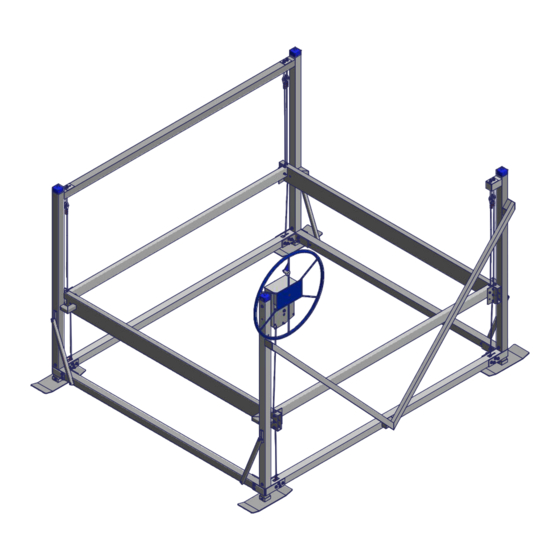
- Page 11 WINCH / WHEEL INSTRUCTIONS STEP 1 Remove the Winch Cover by unscrewing the three screws. Step 2 Attach the Winch and Winch Support Plate to the Lift Side Upright. Secure with two Bolts ½ x 5, four Washers Flat ½ and two Nuts ½ - as shown in Detail “A”.
- Page 12 STEP 3 Set Screw Slide end of cable into slotted opening on winch hub. Using a 3/16" Allen Wrench, tighten winch hub set screw to secure cable to winch hub. Cable Hole NOTE: Cable must enter at slotted end of opening In Slot through hub as shown.
- Page 13 STEP 5 Thread Wheel clockwise on to shaft of Winch.You must thread wheel all the way on winch shaft. The wheel hub must be fully against brake pad when turning wheel up! STEP 6 Using a sharp knife or razor blade, cut a small hole in the middle of the wheel, where the wheel sticker covers the attaching bolt hole.
- Page 14 Proper Cable Locations Right Rack Side Cable Eye Bolt Rear Rack Cable Eye Bolt Front Rack (winch) Cable Eye Bolt Left Rack Side Cable Eye Bolt Rear Rack Cable Attached here Right Rack Side Cable Attached Here Front of Lift Left Rack Side Cable Attached Here CAUTION...
- Page 15 Proper Cable Adjustment a) There are four cables with Eye Bolts and nuts that must be adjusted to properly level cables. These Eye Bolts are all located near the rear uprights as shown. b) Turn wheel so front rack beam raises about 6" above the bottom of frame. Adjust cables so all corners of rack are the same distance from frame.
-
Page 16: Installation Instructions
If they are not, adjust the legs accordingly. Note: If the lift legs will extend 3 feet or more, ShoreMaster recommends deep water braces to stabilize and strengthen the lift. Ask your dealer for more information. - Page 17 OPERATING INSTRUCTIONS CAUTION When first using the boat lift after installation, the weight of the boat may cause the lift to settle and become unbalanced. Until you are certain the lift has stabilized, make sure people are not in the immediate vicinity of the lift.
- Page 18 5. Check and lubricate pulleys to ensure that they are turning freely. 6. Check Eye-Bolts to make sure they are not working themselves loose. ShoreMaster dealers usually offer service visits. Please contact them if you are unable or unwilling to perform maintenance or service to lift.
- Page 19 “zincs” constitutes “abuse” as used herein. (p) Products that are noted with a “(p)” are Prorated. Prorated means that ShoreMaster will provide a Credit, as defined herein, toward your purchase of a replacement product or part. Credit = ([months remaining in the Parts Warranty...
-
Page 20: Warranty
ShoreMaster will provide freight from ShoreMaster’s facility to the local ShoreMaster dealer or distributor on the next truck or container that is sent to the local ShoreMaster dealer or distributor during the normal course of business.
Need help?
Do you have a question about the 701068 and is the answer not in the manual?
Questions and answers