
Related Manuals for Telkom Telmor WWK-9103


Summary of Contents for Telkom Telmor WWK-9103
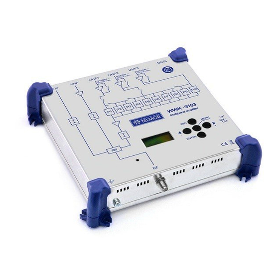
- Page 1 WWK-9103 Programmable Multiband Amplifier User Manual IO-7538-355-01 GZT TELKOM-TELMOR Sp. z o.o., ul. Schuberta 104, 80-172 Gdańsk, Poland T: +48(58) 3823 349, e-mail: export@telmor.pl, www.telmor.pl...
-
Page 2: Table Of Contents
Contents 1. General ........................................ 3 2. Safety-related information @ IMR3- 60dBc ........................... 3 3. Installation of control unit ..............................4 3.1 Connecting the WWK-9103 ..............................4 4. Programming ................................5 4.1 Return to default settings ..............................5 5. Configuration ........................................ 6 5.1 Principle of operation ............................... -
Page 3: General
WWK-9103 enables to receive these signals, to equalize their levels and to amplify them. The WWK amplifier can be used as an independent unit, as well as a part of a bigger head-end station.. -
Page 4: Installation Of Control Unit
During the installation of control unit or works on cabling, we recommend that the power cable be unplugged. 3.1 Connecting the WWK-9103 Note: the UHF inputs are equipped with remote on/off power supply which can be switched. The possible voltage is 12 or 24 V, max. 80 mA. -
Page 5: Programming
Programming The device is programmed using the display and a 5-button keypad. The programming procedure for individual parameters is given below. Return to the previous menu ( - browse the menu, - decrease the displayed value "-" - browse menu functions, - increase the displayed value "+"... -
Page 6: Configuration
Configuration After powering up, the unit is in standby mode; the display shows the sign =. 5.1 Principle of operation Press any button to get access to the configuration menu in standby mode. In brief: Use + / - to navigate the menu; ... -
Page 7: Operation Diagram
Operation diagram GZT TELKOM-TELMOR Sp. z o.o., ul. Schuberta 104, 80-172 Gdańsk, Poland T: +48(58) 3823 349, e-mail: export@telmor.pl, www.telmor.pl... -
Page 8: Block Diagram
Block diagram GZT TELKOM-TELMOR Sp. z o.o., ul. Schuberta 104, 80-172 Gdańsk, Poland T: +48(58) 3823 349, e-mail: export@telmor.pl, www.telmor.pl... -
Page 9: Technical Specification
Technical specification DESIGNATION WWK-9103 Inputs UHF1 UHF2 UHF3 Max. output level Input Noise ratio Gain control 0 to 20 UHF gain control 0 to 20 VHF/UHF max. output level (IM3-60dB) dBµV Filters arrangement Width of filtering channels 8 to 56 Filter selectivity up to ±...
Need help?
Do you have a question about the WWK-9103 and is the answer not in the manual?
Questions and answers