Table of Contents
Advertisement
Quick Links
Advertisement
Table of Contents

Related Manuals for TTI 151476 Series


Summary of Contents for TTI 151476 Series
- Page 1 ELECTRICIAN’S MULTIMETER PART NO: TTIDM1000V (..151476) OPERATING INSTRUCTIONS...
-
Page 2: Table Of Contents
CONTENTS INTRODUCTION ......................3 • Intended Use ........................3 • Product Contents ......................3 • Electrical Symbols ......................3 GENERAL SAFETY ......................4 SAFETY INSTRUCTIONS ....................4 • Safety Standards .......................4 • Safety Instructions ......................4 GENERAL SPECIFICATIONS ..................6 EXTERNAL OVERVIEW ....................6 • Functional Dial Overview ....................7 •... -
Page 3: Introduction
INTRODUCTION TTIDM1000V is a professional digital multimeter with the following features: HVAC temperature measurement Non-contact voltage detection AC/DC current measurement up to 20A AC/DC voltage measurement up to 1000V hFE function Diode test INTENDED USE This multimeter is to be used only for electrical inspection within the specifications the machine is rated for. -
Page 4: General Safety
GENERAL SAFETY Prior to using the multimeter, please read the product manual and ensure you have a solid understanding of the multimeter’s functions and features. The warnings, cautions, and instructions discussed in this instruction manual cannot cover all possible conditions or situations that could WARNING occur. - Page 5 • Connect the common test lead before the live test lead and remove the live test lead before the common test lead. • Do not use a current measurement as an indication that a circuit is safe to touch. A voltage measurement is necessary to know if a circuit is hazardous.
-
Page 6: General Specifications
GENERAL SPECIFICATIONS Max voltage between input terminal and ground: please refer to the technical index for more details. 20A terminal: 20A 250V fast-acting fuse ( 5x 20mm) mA/µA terminal: 600mA 250V fast-acting fuse ( 5x20mm) Display count: 6000 Max capacitance: 100mF Range: Manual Polarity: Auto Refreshes 2-3 times/s;... -
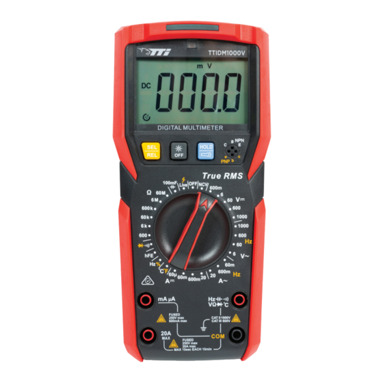
Page 7: Functional Dial Overview
FUNCTIONAL DIAL OVERVIEW POSITION DESCRIPTION DC voltage measurement AC voltage measurement AC current measurement 100mF Live 600m DC current measurement Contact-type live/neutral wire Live 600k measurement 1000 Shut-down 1000 Frequency/ duty radio measurement Non-contact voltage measurement Transistor measurement °C°F 600m 60µ... -
Page 8: Lcd Screen Overview
LCD SCREEN OVERVIEW SYMBOL DESCRIPTION Caution AC/DC voltage is higher than 30V Data hold Negative reading AC/DC AC/DC measurement Low battery indicator Diode measurement Continuity measurement MKΩ Relative value measurement Ω, k Ω, M Ω Resistance unit mV, V Voltage unit μA, mA, A Current unit Auto... -
Page 9: Buttons Overview
BUTTONS OVERVIEW BUTTON DESCRIPTION • Continuity/diode: short press (<2s) to cycle through continuity and diode measurement. • Hz%: short press (<2s) to cycle through frequency and duty ratio measurement. • ACV: short press {<2s) to cycle through frequency and AC voltage measurement. •... -
Page 10: Operating Instructions
OPERATING INSTRUCTIONS If the battery voltage is low when the device is turned on, “ ” symbol will appear on the screen. User needs to replace batteries in time before use. Please also pay special attention to the warning sign “ “... -
Page 11: Ac Voltage Measurement
AC VOLTAGE MEASUREMENT Do not input voltage over 1000Vrms. It is possible to measure higher WARNING voltage. However, it may cause damage to the meter. Be cautious to avoid electric shock when measuring high voltage. Switch the function dial to position (range: 6V/60V/600V/1000V). -
Page 12: Ac/Dc Current Measurement
AC/DC CURRENT MEASUREMENT • To prevent possible electric shock, fire or personal injury, switch off the power supply of the circuit before measuring the current, and then connect the meter with the circuit in series. • Use the proper terminals, switch position, and range for your WARNING measurement. -
Page 13: Resistance Measurement
RESISTANCE MEASUREMENT • To avoid damaging the meter or to the device under test, disconnect circuit power and discharge all the high-voltage capacitors before WARNING measuring resistance. • To avoid electric shock, do not input higher than DC 60V or AC 30V voltages. -
Page 14: Diode Measurement
DIODE MEASUREMENT • To avoid possible damage to the meter and to the device under test, disconnect circuit power and discharge all high-voltage capacitors WARNING before testing diodes. • To avoid electric shock, do not input higher than DC 60V or AC 30V Switch the function selector to position. - Page 15 Indicator Indicator TTIDM1000V TTIDM1000V HOLD HOLD True RMS True RMS 100mF 100mF Live Live 600m 600m Ω Ω 600k 600k 1000 1000 1000 1000 °C°F °C°F 600m 600m 60µ 60µ 600m 600m mA µA mA µA VΩ °C VΩ °C FUSED FUSED CAT II 1000V...
-
Page 16: Continuity Measurement
CONTINUITY MEASUREMENT • To avoid damaging the meter or to the device when testing, disconnect circuit power and discharge all the high-voltage capacitors before WARNING testing for continuity. • To avoid electric shock, do not input higher than DC 60V or AC 30V Switch the function dial to the position, and make sure the circuit power is turned off. -
Page 17: Capacitance Measurement
CAPACITANCE MEASUREMENT Please fully discharge all capacitors before measuring (especially WARNING for capacitors with high voltage) to avoid damage to the meter and personal injury. Switch the function dial to position, the green indicator should be on. 100mF Connect the common test lead to COM terminal, then insert red test lead to Ω... -
Page 18: Frequency/Duty Ratio Measurement
FREQUENCY/DUTY RATIO MEASUREMENT Do not input voltage higher than DC 60V or AC 30V to avoid WARNING personal injury! Switch the function selector to position the green indicator should be on. Connect the common test lead to COM terminal, then insert red test lead to Ω... -
Page 19: Temperature Measurement
TEMPERATURE MEASUREMENT Switch the function dial to °C°F position. Plug the K-type thermocouple “+” end to terminal and the other end to Ω °C COM terminal. Short press (<2s) SEL/REL button to switch between°C°F. NOTE: • “OL” symbol appears when the meter is turned on. •... -
Page 20: Transistor Measurement
TRANSISTOR MEASUREMENT Do not input any voltage at any test lead terminals during the WARNING transistor measurement to avoid personal injury! Switch the function selector to hFE position, make sure that the lest leads aren’t connected to any circuit Insert the three pins of the transistor to the socket according to the polarity The reading on the screen is the amplification factor of the measuring transistor. -
Page 21: Non-Contact Voltage Measurement (Ncv)
NON-CONTACT VOLTAGE MEASUREMENT (NCV) Switch the function dial to position. In NCV sensing level 2 (default, LCD displays “EFHI”), the voltage range is 48V–220V. Place the upper left corner of the multimeter near the live AC power cord. If the voltage of the measured power cord is in the range of sensing level 2, the yellow indicator will start flashing and the buzzer will beep intermittently. -
Page 22: Contact Type Live/Neutral Wire Management
CONTACT TYPE LIVE/NEUTRAL WIRE MANAGEMENT • Do not input voltage over 1000Vrms. It is possible to measure higher voltage. WARNING However, it may cause damage to the meter. • Be cautious to avoid electric shock when measuring high voltage. Switch the function selector to Live position. Connect the red test lead to terminal. -
Page 23: Technical Index
TECHNICAL INDEX • Accuracy: ±(a% of reading + b digits) • Ambient temperature: 23°C ±5°C (73.4°F ±9°F) • Relative humidity: <75% DC VOLTAGE MEASUREMENT RANGE RESOLUTION ACCURACY 600mV 0.1mV ± (0.5%+4) ± (0.7%+3) 10mV ± (0.7%+3) 600V 100mV 1000V ± (0.7%+10) Input impedance: *mV range >1000MΩ, *other ranges: about 10MΩ. -
Page 24: Resistance Measurement
• According to the crest factor, the additional error is calculated as follows: a. Add 4% when crest factor is 1-2 b. Add 6% when crest factor is 2-2.5 c. Add 8% when crest factor is 2.5-3 • AC voltage frequency measurement: 45Hz-1kHz. Min measurement amplitude: 10% of voltage range. -
Page 25: Transistor Measurement
TRANSISTOR MEASUREMENT RANGE RESOLUTION REMARK β β (NPNP/ NP)Vce1.8Z , lb0 5µA 1000 CAPACITANCE MEASUREMENT RANGE RESOLUTION ACCURACY ± (5%+35) 60nF 10pF 600nF 100pF ± (2.5%+20) 60uF 10nF 600uF 100nF 1μF ± (6.0%+10) 60mF 10μF ± (10%+0D) 100.0mF 100μF ± (10%+0D) Overload protection: 600V-PTC •... -
Page 26: Ac Current Measurement
AC CURRENT MEASUREMENT RANGE RESOLUTION ACCURACY RANGE RESOLUTION ACCURACY 60mA 60mA 10µA ±(1.0%+12) 10µA ±(1.5%+12) (45~400Hz) (400 - 1000Hz) 600mA 600mA 0.1mA ±(2.0%+3) 0.1mA ±(2.5%+5) (45~400Hz (400 - 1000Hz) 10mA ±(3.0%+5) 10mA ±(3.5%+8) (45~400Hz) (400 ~ 1000Hz) • True RMS display. Frequency response: 45~1KHz •... -
Page 27: Temperature Measurement
TEMPERATURE MEASUREMENT RANGE RESOLUTION ACCURACY 40°C~0°C 1°C ± (6%+5) 0°C~400°C 1°C ± ( 2%+4) 400°C~1000°C 1°C ± ( 2%+5) -40° F- 32° F 1° F ± (6%+9) 32 °F~752°F 1° F ± (2%+8) 752°F~1832 ° F 1° F ± (2%+9) Overload protection: 600V-PTC 10.11 LED THREE COLOUR INDICATOR FUNCTION... - Page 28 LED THREE COLOUR INDICATOR CONTINUED LED on (green) Amplification factor >50 Transistor LED on (yellow) Amplification factor 50 LED off Amplification factor = 0 LED off <20pF Capacitance LED on (green) The capacitor is fully charged LED on (yellow) The capacitor is charging LED off DCV <1000V, ACV <1000V Voltage...
-
Page 29: Maintenance
MAINTENANCE Do not attempt to repair or service the meter unless you are qualified WARNING to do so and have the appropriate calibration, performance test and service tools. If not, consult you Total Tools store for repair/service. To avoid electrical shock or damage to the meter, do not get expose the meter to water or have it submerged in water. - Page 30 ELECTRICIAN’S MULTIMETER...
- Page 31 OPERATING MANUAL...
-
Page 32: Warranty Information
WARRANTY INFORMATION This warranty is provided by Total Tools (Importing) Pty Ltd of 20 Thackray Road, Port Melbourne VIC 3207. Phone: 03 9261 1900 (we, us, our). Express Warranty Subject to the exclusions set out below, we warrant that this product will be free from defects in materials or workmanship for 12 months from the date of purchase.
Need help?
Do you have a question about the 151476 Series and is the answer not in the manual?
Questions and answers