Advertisement
Table of Contents
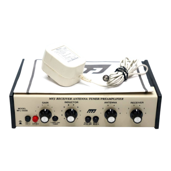
Introduction
The MFJ-959B RECEIVER ANTENNA TUNER/PRE-AMPLIFIER is designed to
properly match your antenna to your receiver for better performance from 1.8 to
30 MHz with a single antenna.
Maximum signal power transfer occurs when the impedance of the antenna
matches the impedance of the receiver. This will happen at specific frequencies
as determined by the length of the antenna. At these frequencies a tuner is not
needed. If the antenna is used at frequencies other than the resonant
frequencies, the signal from the antenna to the receiver may be significantly
reduced due to the mismatch of the antenna to the receiver. The MFJ-959B can
transform the antenna impedance to match that of the receiver for maximum
signal. The MFJ-959B also has a broadband transistor pre-amplifier to help
boost signals to a copyable level which is especially helpful on the older
receivers which lack sensitivity. A 20 db attenuator is also built in to help
receivers plagued with overload problems from strong signals.
Installation
1. Plug the 12V AC adapter into the power jack on the MFJ-959B, then plug the
adapter in to the 110 AC wall socket. If 110V AC is not available, plug external
power of 9-18V DC into the rear panel power jack. The tip of the subminiature
plug is positive and the sleeve is ground.
2. Connect your receiver antenna input to one of the two output connectors on
the MFJ-959B marked RECEIVER. There are two sets of outputs for use with
2 radios and each output has an SO-239 connector and an RCA phono jack
connected in parallel for added convience.
3. Connect the antenna to one of the ANTENNA connections on the MFJ-959B.
There are two sets of inputs. Each input has both an SO-239 connector and
an RCA phono jack for the antenna connection. For best results when using a
random wire antenna with the MFJ-959B, the wire should be 1/4 wave or
longer at the lowest receiving frequency.
Operation
1. Set the RCVR & ANT pushbutton switches to the desired position to select the
proper receiver and antenna.
2. Set the ON-OFF/BYPASS pushbutton switch to the OFF/BYPASS position
(This bypasses the MFJ-959B).
.
MFJ-959B INSTRUCTIONS
1
Advertisement
Table of Contents

Related Manuals for MFJ MFJ-959B


Summary of Contents for MFJ MFJ-959B
- Page 1 Installation 1. Plug the 12V AC adapter into the power jack on the MFJ-959B, then plug the adapter in to the 110 AC wall socket. If 110V AC is not available, plug external power of 9-18V DC into the rear panel power jack.
- Page 2 4. Set the ON-OFF/BYPASS switch to ON. 5. Set the TUNER/AMP-TUNER switch to TUNER. 6. Turn the ANTENNA and RECEIVER controls on the MFJ-959B to about mid scale and rotate the INDUCTOR switch for maximum signal. On the higher bands, the ANTENNA and RECEIVER controls may need to be set to 3/4 scale to find the maximum signal of the inductor.
Need help?
Do you have a question about the MFJ-959B and is the answer not in the manual?
Questions and answers