Advertisement
Quick Links
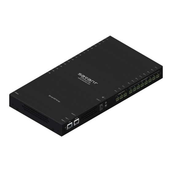
Savant® SmartEnergy Monitor (SEM-1024)
Quick Reference Guide
Box Contents
(1)
SmartEnergy Monitor (SEM-1024-xx)
(1)
Installation Kit Energy Monitor (075-0101-xx)
(1)
Power Supply 12V AC 1A (025-0187-xx)
(24) Screw down plug-in 2 pin connectors (028-9394-xx)
(4) Screw M3 x 8mm Flat Phil Black (039-0017-xx)
(2) Side Mount Chassis Bracket (071-0628-xx)
(1)
SEM Current Transformer ID Labels (1 sheet) (083-0042-xx)
(1)
Quick Reference Guide (this document)
Optional Accessories
– SEM-VT01 - SmartEnergy Voltage Sensors
– CON-SDC2 - 2 pin screw-down connectors (25 pack)
– Split Core Current Transformers (clamp-on style)
• SEM-020A5
20A
• SEM-050A5
50A
• SEM-150A1
150A
• SEM-150A5
150A
• SEM-250A1
250A
• SEM-400A1
400A
• SEM-600A1
600A
IMPORTANT!
The SEM-250A1, SEM-400A1 and SEM-600A1 are
supported from da Vinci 5.2.3 and higher.
Specifications
Environmental
Temperature
32° to 104° F (0° to 40° C)
Humidity
5% to 95% Relative Humidity (non-condensing)
Maximum BTU's
27 BTU/hr
Cooling
1 cubic feet per minute (CFM) recommended
Dimensions and Weight
Height
12.51 in (31.78 cm)
Width
6.48 in (16.46 cm)
Depth
1.30 in (3.30 cm)
Weight
Chassis 4 lb (1.81 kg) Shipping: 6.0 lb (2.72 kg)
Power
Input Power
12V AC
Max Power
8 Watts
Regulatory
Safety and Emissions
RoHs
Compliant
Minimum Supported Release
SEM-1024
Current Transformers
20, 50, and 150 Amps
Current Transformers
250, 400, and 600 Amps
Additional Information
Additional Information is available on the Customer Community.
– SEM-1024 SmartEnergy Technical Specifications (009-0521-xx)
– SEM-1024 SmartEnergy Deployment Guide (009-1024-xx)
– SEM-1024 SmartEnergy Monitor Deployment Guide (009-0419-xx)
– SEM-1024 SmartEnergy User Guide (009-0420-xx)
Important Information
– All wiring in the United States must be installed in accordance with
the latest adopted edition of the National Electrical Code (ANSI/
NFPA 70, NEC).
– All wiring in Canada must be installed in accordance with the latest
adopted edition of the Canadian Electrical Code (CSA C222.2 CEC,
Part 1) and any provincial or local requirements.
– The SEM-1024 supports services that are 600 amps or less. Verify
the main circuit breaker in your panel is not larger than 600 amps.
– The maximum diameter of the wires feeding the main breaker
cannot exceed 1 inch. The SEM-1024 can not operate with larger
conductors.
– Only 500 MCM conductors or smaller are supported.
TIP! MCM is unique to North America and represents the diameter
of a wire. Common MCM sizes are 500, 350, and 250.
– Maximum length for leads on each current transformer should not
exceed 8 feet. Longer lengths will cause inaccurate readings.
– If required, the leads on the current transformers can be shortened.
– The SEM-1024I (International) supports 230V AC 50Hz services.
SEM-1024 | 009-0358-05 | 170208
Copyright 2018 Savant Systems, LLC
8 ft leads
(5 pack)
8 ft leads
(5 pack)
8 ft leads
(1 pack)
8 ft leads
(5 pack)
8 ft leads
(1 pack)
8 ft leads
(1 pack)
8 ft leads
(1 pack)
FCC Part 15
da Vinci 4.3.3 and higher
da Vinci 5.2.3 and higher
Left Panel
Input Channels
1
2
3
4
5
6
7
8
Input ports for each Current Transformer installed in the system.
A
Sixteen ports are available on the left panel and an additional
eight ports are available on the right panel. Total Inputs = 24
Off - SEM-1024 is either not powered or is booting the
embedded firmware.
Green Flashing - Provisioned to the local network (has
IP address) but not yet communicating with the Host.
Green - Provisioned to the local network and commu-
nicating with the Savant System Host.
Red - Savant System Host has determined a firmware
Status
B
LED
update is required. However, a problem occurred
during the update process that will initiate a reset.
Red Flashing - Embedded firmware is running but has
not received an IP Address.
Amber - Firmware is updating.
Amber Flashing - A link-local IP Address is established
and SEM-1024 is waiting to connect to the Host.
Right Panel
A
D
Data
RS232
Reset
B
C
Press and hold for five seconds then release to
A
Reset Button
clear the network settings. After the reset, the
default DHCP mode is restored.
10/100 Base-T auto-negotiating
Data Speed
B
Green - 100 Mb speed
LED
Off - 10 Mb speed
10/100 Base-T auto-negotiating
Data Activity
C
LED
Orange - Ethernet data activity
D
RS-232 Port
Reserved for future use
Connect the included power supply between
E
12V AC Input
120V AC and the 12V AC port.
Connect a #18 AWG wire between this Gnd
screw and a good grounding point. Making this
connection will achieve a greater level of safety
F
Gnd
from electrical hazards and electromagnetic
interference (EMI). Savant recommends making
Gnd screw connection.
Voltage
Voltage sensor input ports. Input port for the
G
SEM-VT01 voltage sensor.
Sensors
Input
H
Additional Current Transformer input ports.
Channels
Current Transformer and Voltage Sensor Input Polarity
The polarity of the inputs for the Current Transformer and Voltage
Sensor inputs on the SEM-1024 are shown below.
Current Transformer Input
POS (+) - White or red wire from Current
Transformer.
GND (-) - Black wire from Current Transformer
POS(+) GND (-)
Voltage Sensor Input
POS (+) - Connect to the positive (+) output
on Voltage Sensor. See diagram in the
Voltage Sensors
GND (-) - Connect to the GND output of a
POS(+) GND (-)
Voltage Sensor (SEM-1024). See diagram in
Install Voltage
1
of
2
A
9
10
11
12
13
14
15
16
E F
G
Voltage Sensor
12VAC
3
2
1
24
23
22
section.
Sensors.
45 Perseverance Way, Hyannis, MA 02601
Savant.com
For Product Info
B
Status
H
Input Channels
21
20
19
18
17
Install
| 508.683.2500
Advertisement

Related Manuals for Savant SEM-1024


Summary of Contents for Savant SEM-1024
- Page 1 Part 1) and any provincial or local requirements. Voltage Sensor Input – The SEM-1024 supports services that are 600 amps or less. Verify POS (+) - Connect to the positive (+) output the main circuit breaker in your panel is not larger than 600 amps.
- Page 2 From 3-Phase not over-tighten. Electrical Panel 4. Set the SEM-1024 onto the wall where it will be mounted. The SEM-1024 can be positioned with ports facing vertically or hori- Connect Voltage zontally. Level the unit and mark on the wall the mounting holes in Sensor to each Phase the two brackets.