Savant SmartEnergy SEM-1024 Quick Reference Manual
Hide thumbs
Also See for SmartEnergy SEM-1024:
- Quick reference manual (2 pages) ,
- Deployment manual (24 pages)
Table of Contents
Advertisement
Quick Links
The Savant SmartEnergy Monitor (SEM-1024) Quick Reference Guide provides the
information necessary to install and operate the SEM-1024 and associated components.
Box Contents
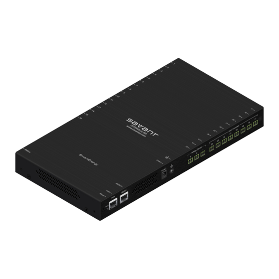
(1) SmartEnergy Monitor (SEM-1024-xx)
(1) Installation Kit Energy Monitor (075-0101-xx)
• (1) Power Supply 12VAC 1A (025-0111-xx)
• (24) Screw-down, 2-pin termination connectors (028-9394-xx)
• (4) Screw M3 X 8MM Flat Phil Blk (039-0017-xx)
• (2) Side Mount Chassis Bracket (071-0628-xx)
• (24) Current Transformer ID labels (1 sheet) (083-0042-xx)
(1) Quick Reference Guide (this document)
Optional Accessories
Current Transformers, Voltage Sensors and additional termination connectors are also
available and sold separately based on the needs of your specific energy monitoring
installation.
•
SEM-150A1, 150 Amp clamp-on current transformer, 8 ft lead (1 pack)
•
SEM-150A5, 150 Amp clamp-on current transformers, 8 ft leads (5 pack)
•
SEM-050A5, 50 Amp split core clip-on current transformers, 8 ft leads (5 pack)
•
SEM-020A5, 20 Amp split core clip-on current transformers, 8 ft leads (5 pack)
•
SEM-VT01, Smart Energy Voltage Sensors
•
CON-SDC2 2-pin screw-down termination connectors (25 pack)
Specifications
Environmental
Operating Temperature
32º to 104º F (0º to 40º C)
Operating Humidity
5% to 95% Non-condensing
Maximum BTUs
27 BTUs per hour
Cooling
1 cubic feet per minute (CFM) recommended
Physical
Dimensions (H x W x D)
12.51 x 6.48 x 1.30 in (31.79 x 16.46 x 3.30 cm)
Weight
4 lbs (1.82 kg)
Power
Maximum Power
8W
Power Supply
12V AC
Regulatory
Safety and Emissions
FCC Part 15
RoHS
Compliant
Left Side
1
Input Channels (1-16)
2-pin termination connectors attach to Input Channels from
(left side-positive, right
current transformers (CTs).
side-ground)
2
Status LED (bi-color)
• Green indicates the Host has established
communications with the embedded system.
• Green flashing indicates the embedded system is ready
(running with DHCP IP address), but the Host has not
established communications with the embedded system.
• Off indicates the embedded processor is resetting or is
not powered up; or is booting the embedded firmware.
• Red indicates the Host has determined the firmware
needs to be updated, but a problem occurred during the
process that will initiate a reset.
• Red flashing indicates the embedded firmware is
running, but has not received a DHCP IP Address.
• Amber indicates the Host is currently updating the
embedded firmware.
• Amber flashing indicates the embedded system has a
valid link-local IP Address and is waiting to connect to the
Host.
Right Side
1
2 3
4
5
1
Reset button
Resets the factory default DHCP mode. Press and hold the
Reset button for 5+ seconds.
2
Data Ethernet Speed
10/100 Base-T, auto-negotiating port
LED
Green indicates an Ethernet speed of 100 Mb, when Off
indicates an Ethernet speed of 10 Mb.
3
Data Ethernet Activity
10/100 Base-T, auto-negotiating port
LED
Orange indicates Ethernet data activity.
4
RS232 serial port
RJ-45 port used to transmit and receive serial binary data
transmission. Reserved for future use.
5
12VAC input power
Connects 12V AC input power to SEM-1024.
6
Savant recommends using the ground connector to achieve
a greater level of safety from electrical hazards to persons
and protection from electromagnet interference (EMI).
7
Voltage Sensors (1-3)
2-pin termination connectors attach to SmartEnergy Voltage
Sensors; line input for each of 3 separate phases.
8
Input Channels (17-24)
2-pin termination connectors attach to Input Channels from
current transformers (CTs).
Input Channel and Voltage Sensor Connector Polarities
Ensure the black wire is connected to right side of the 2-pin termination connector when
connecting to the CT and VT inputs on the SEM-1024.
Copyright © 2012 Savant Systems LLC, SAVANT and RacePoint Blueprint are trademarks of Savant Systems, LLC.
All brand names, product names and trademarks are the property of their respective owners.
Savant Systems, LLC reserves the right to change product specifications without notice.
45 Perseverance Way, Hyannis, MA 02601
SmartEnergy Monitor
Quick Reference Guide
6
7
8
Note - When connecting to the VT transformer, refer to the External Voltage Sensor (SEM-
VT01) diagram on the next page.
SmartEnergy Monitor Considerations
Safety
CAUTION - Any task requiring the removal of the electrical panel cover MUST be performed
by an electrician or qualified individual. All local electrical codes and rules must be obeyed.
Every effort has been made in providing for the safe and secure installation of the
SmartEnergy Monitor. The installation of the SEM-1024 requires the removal of the cover of
the main electrical circuit breaker panel. After the circuit breaker panel cover has been
removed, the potential hazard of shock, burn, or even electrocution now exists.
Do not attempt to complete this installation unless you are very familiar with the electrical
components and operation of the circuit breaker panel. Even when the main circuit breaker
has been turned to the "OFF" position, certain areas within the circuit breaker panel may still
be electrified. Do not attempt installation unless you know where these electrified areas are.
WARNING - These servicing instructions are for use by qualified personnel only. To reduce
the risk of electric shock, DO NOT perform any servicing other than that contained in these
operational instructions, unless you are qualified to do so.
Before You Start
Do not begin installation until you have read the "Safety" section of this manual, and read all
instructions before beginning the installation.
Estimated Installation Time:
professional installer—dependent on the number of current transformers, number of
SmartEnergy monitors, single-phase or 3-phase installations, and the complexity of the
energy-monitoring configuration.
All wiring in the United States must be installed in accordance with the latest adopted edition
of the National Electrical Code (ANSI/NFPA 70, NEC) and state or local requirements. All
wiring in Canada must be installed in accordance with the latest adopted edition of the
Canadian Electrical Code (CSA C22.2 CEC, Part I) and any provincial or local requirements.
The SEM-1024 setup includes the following:
Installation Site
Ensure the SEM-1024 installation site provides adequate ventilation for proper cooling and
space to access the SEM-1024 panel connectors. If mounting on the wall, Savant
recommends using the supplied mounting brackets.
Limitations
Review the following SmartEnergy Monitor operational limitations.
Current Transformers (CTs)
• SEM-1024 is only suitable for services of 200 Amps or less, or 400 Amps with parallel
200A feeds.
• SEM-1024 is only suitable for services with maximum 350 MCM conductors.
Note: MCM = A circular mil (CM) is a figure that represents the cross-sectional area of
a circular-section conductor whose diameter is one mil (i.e. one-thousandth of an
inch). Common MCM sizes in the electrical trade are 500, 350, 250, and the circular
mil is a measurement unique to North America.
• If your main circuit breaker or fuse panel is larger than 200 Amps, SEM-1024 WILL
NOT work.
• If your main service circuit conductors (wires) are larger than 1-inch diameter, SEM-
1024 WILL NOT work.
• Savant recommends that you DO NOT increase the lengths current transformer leads,
which are 8 feet. Increasing the lead lengths may cause inaccurate measurements.
The lead lengths can be decreased without causing inaccurate measurements.
Power Supply
• If you have a 230V AC 50Hz service typical in most areas outside North America,
SEM-1024 WILL NOT work.
Important: The SEM-1024I (International) version is required for 230V AC 50Hz
installations.
Installation
To install the current transformers, voltage sensors and SmartEnergy Monitor (SEM-1024)
unit, do the following:
IMPORTANT - Turn off all power to the circuit breaker panel by turning off the main
breaker or main switch.
1.
Turn off all power to the circuit breaker panel.
2.
Remove circuit breaker panel cover by following the SAFETY instructions.
Installing and Connecting the Current Transformers (CTs)
CAUTION - Only use Savant suppled current transformers with the SEM-1024/SEM-
1024I. All Savant current transformers are internally shunted (333 mV at rated current),
and therefore, inherently safe compared to other commercially available CTs. In
addition, they are also calibrated for optimal performance with the SEM-1024/SEM-
1024I.
CAUTION - If this is a combination panel, the lugs on the primary side of the main
breaker are probably still hot.
CAUTION - The CT installation along with any other task requiring the removal of the
electrical panel cover MUST be performed by an electrician or qualified individual. All
local electrical codes and rules must be obeyed.
Phone 508.683.2500
Fax 508.683.2600
Thirty minutes to several hours when performed by a
Savant Confidential and Proprietary
www.SavantSystems.com
009-0358-03
SEM-1024-00
Advertisement
Table of Contents

Subscribe to Our Youtube Channel
Related Manuals for Savant SmartEnergy SEM-1024


Summary of Contents for Savant SmartEnergy SEM-1024
- Page 1 MUST be performed by an electrician or qualified individual. All local electrical codes and rules must be obeyed. Copyright © 2012 Savant Systems LLC, SAVANT and RacePoint Blueprint are trademarks of Savant Systems, LLC. All brand names, product names and trademarks are the property of their respective owners.
- Page 2 Install the Current Transformers as follows: Savant requires a licensed electrician to wire from the high voltage side (primary) of the main • The 20A and 50A CTs must be installed with the arrows pointing in the direction of the electric panel box to the voltage transformer to meet the electrical codes of the municipality.
Need help?
Do you have a question about the SmartEnergy SEM-1024 and is the answer not in the manual?
Questions and answers