Subscribe to Our Youtube Channel
Summary of Contents for Sakura Dry-Boy SDB-55
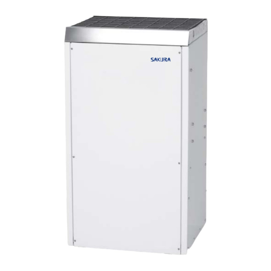
- Page 1 Dry-Boy Hi g h Ef f i cien cy D ehu mi di fi er SAKURA Basement Air System (for Basement / Crawlspace Dehumidification) M o d e l : S D B - 5 5 Installer’s & Owner’s Manual...
- Page 2 TABLE OF CONTENTS Table of Contents 11. Maintenance ................... 5 11.1 Air Filter .................. 5 1. Specifications ................... 2 12. Service ................... 6 2. Installation ..................3 12.1 Warranty ................. 6 2.1 Location ..................3 12.2 Technical Description ..............6 2.1A In Humid Area, No Ducting ........... 3 12.3 Troubleshooting..............
- Page 3 2.1A In humid area, no ducting. The simplest installation is to place SAKURA Dry-boy in the humid If SAKURA Dry-boy is located too far from a floor drain for the area with no ducting. The air inlet on top & outlet on the side attached hose to reach, 1/2"...
- Page 4 INSTALLER'S AND OWNER'S MANUAL controller to excessively low levels in cool rooms. Doing so will 6. MEMORY/POWER FAILURE result in long periods of ineffective dehumidifier run time. An ideal If a power failure occurs, the owner must press the ON/OFF button setting is 55%, which prevents mold growth.
- Page 5 6 minutes and then exit the DEFROST MODE. 11.1 Air Filter SAKURA Dry-Boy is equipped with two (2) air filters. An aluminum/ 8.6C The DEFROST CYCLE LED will be extinguished. foam pre-filter followed by a standard MERV-11 65% efficient pleated fabric filter.
- Page 6 12.2 Technical Description compresses it to a high pressure and temperature gas to repeat SAKURA Dry-Boy uses a refrigeration system similar to an air the process. conditioner’s to remove heat and moisture from incoming air and add heat to the air that is discharged (see Figure 1).
-
Page 7: Service Parts List
SERVICE PARTS LIST DESCRIPTION SPECIFICATIONS Wheel Plate, Bottom Galvanized steel (1.5mm) Bracket Galvanized steel (1.0mm) Grommet, rubber – compressor Buna N Washer, plate 6mm dia. Steel M6 steel Capacitor, compressor 35µF/250V Compressor 5RS080UAA21 115VAC/60HZ R410A Gasket, cover – terminal Spring, hold down Overload protector B290-150-241H Cover, terminal... - Page 8 SERVICE PARTS LIST • Installer’s & Owner’s Manual...
- Page 9 CONDENSATE PUMP INSTALLATION INSTRUCTIONS STEP 1: The condensate pump kit STEP 2: Predrilled mounting holes are located STEP 3: Secure the condensate pump to the includes:drain hose, condensate pump, two near the bottom and on the same side of the unit with the two provided screws.
- Page 10 DUCTABLE INLET MOUNTING Ductable Inlet Instructions Exhaust Collar Mounting Instructions 1. Remove the Filters from the unit. 5. Remove the exhaust collar from the box and bend the tabs in. 2. Remove the ductable inlet from the box and remove the 6.
- Page 11 MUFFLER KIT INSTRUCTIONS Component List On SAKURA Dry-Boy, the muffler kit (1) Silencer and condensate pump kit may be (2) #8 Screws used together, but the pump will not (1) Instructions be able to be mounted to the unit. Loosen (1) existing screw...


Need help?
Do you have a question about the Dry-Boy SDB-55 and is the answer not in the manual?
Questions and answers