
Related Manuals for ARMTEL IPN-8U


Summary of Contents for ARMTEL IPN-8U
- Page 1 IPN-8U Network switching module ARMT.665200.006UM User Manual Document version 14 26.30.11.120 2021...
- Page 2 © Armtel info@armtel.com...
-
Page 3: Introduction
USER MANUAL INTRODUCTION This User Manual applies to various versions of the IPN-8U Network switching mod- ule ARMT.665200.006 manufactured by Armtel LLC, and is intended to familiarize the User with the device and the procedure for its operation at the installation site. -
Page 4: Safety Provisions
IPN-8U NETWORK SWITCHING MODULE USER MANUAL SAFETY PROVISIONS During installation and operation of IPN-8U, observe the safety measures specified by local regulations on electrical safety. In order to ensure fire safety, follow the rules: − before connecting the product to the power supply, make sure the power and communication cables are properly insulated;... -
Page 5: Table Of Contents
5 STORAGE ..............................25 6 TRANSPORTATION ..........................26 7 DISPOSAL ............................... 27 APPENDIX A (REFERENCE) FUNCTION OF POE IN IPN-8U ............28 APPENDIX B (REFERENCE) PRODUCT CONNECTION ..............30 B.1 IPN-8U subscriber connection cable ..................30 Б.2 Power cable ............................31 armtel.com... -
Page 6: Device Description And Operation
ISDN and Ethernet interface. IPN-8U is installed in telecommunication racks, cabinets located in control and office rooms. IPN-8U operates at temperatures from minus 5 to plus 55 °С at a relative humidity of up to 80%. - Page 7 Note -The manufacturer reserves the right to change the appearance of the prod- uct, which does not affect the installation dimensions and operation of the product. Incorporated into IPN1.1 decentralized communication, IPN-8U module can provide the following functions: − connection of up to eight (8) digital subscriber units with Uk0-interface to a distance of up to 6 km via a copper cable line;...
-
Page 8: Specifications
IPN-8U module using two-color LED indicators on the front panel. Detailed description of the functional area for IPN-8U and its programming method are given in operational documents for IPN 1.1 system, which includes IPN-8U. - Page 9 − IPN-8U with connected 8 DIS units via Uk0-interface, without “phantom” power supply and connected 4 Ethernet ports – 9,1 W. − IPN-8U is a PoE power supply source (injector), which meets the requirements of standard PoE IEEE 802.3af-2003 Class 0 (see Appendix А). Maximum pow- er, given by1 Ethernet port when using the PoE technology is 15.4 W.
-
Page 10: Scope Of Supply
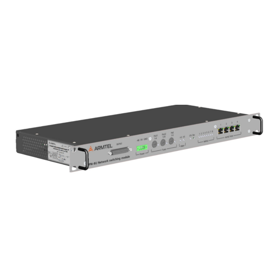
IEEE 802.3af Class 0, and can be used for direct connection of IP subscriber devices. IPN-8U module is housed in 19" metal enclosure with the height of 1HU. On the front panel there are four FastEthernet ports, fuse holders, sockets for power supply and con- nection of digital subscribers. - Page 11 − orange (on the left) –PoE voltage indicator for power supply of the connected unit; − green (on the right) – indicator of Ethernet-connection and its activity. Figure 3 shows fragment of IPN-8U main board with position of control elements. armtel.com page 9/32 info@armtel.com...
- Page 12 − «S3» – block of keys for PoU (phantom power) supply for each of U- interfaces. Numbering of ports on the switch box starts from the back wall of IPN-8U enclosure. At present the switches are not used, because power sup- ply mode on U-interface line is controlled by the configuration data of IPN- 8U module;...
- Page 13 Ethernet interface of the processor is connected to embedded Ethernet switch chip, four of which are connected to the front panel of IPN-8U. Each of these net- work interfaces is equipped with PoE injector (PSE), which provides power to the network devices connected to it.
-
Page 14: Terminal Equipment, Connected To Uk -Interfaces
1.5 Terminal equipment, connected to Uk -interfaces IPN-8U provides for connection and operation of up to eight (8) digital subscriber devices with Uk0-interfaces produced by LLC Armtel. The subscribers connected to IPN-8U can communicate directly with each other, as well as with other subscribers via IP-network. - Page 15 Functional area and configuration parameters of subscriber units, as well as key func- tions, are determined in the configuration data for IPN-8U module and correspond to the capabilities of other subscribers of IPN system described in the document "Decentralized loud-speaking communication system IPN 1.1.
-
Page 16: Labeling
IPN-8U NETWORK SWITCHING MODULE USER MANUAL 1.6 Labeling On the side fasteners of the housing IPN-8U is placed bilingual nameplate, made by laser engraving. The nameplate contains the following information: − name, trademark and reference information of the manufacturer; − product name and description;... -
Page 17: Package
IPN-8U NETWORK SWITCHING MODULE USER MANUAL 1.7 Package IPN-8U with the documents, which come with the supply package, is packed in con- sumer package (cardboard box). A label in Russian language and English language is glued onto the consumer pack- age, said label containing the following inscriptions and symbols: −... -
Page 18: Intended Use
1. Remove the IPN-8U and the connection cables from the shipping container. 2. Remove the IPN-8U and the connection cables from the individual container. 3. Check the completeness of the IPN-8U in accordance with the product passport 4. Visual inspection of unit for damages (cracks, dents, etc.). -
Page 19: Safety Precautions
2. Use any port of integrated FastEthernet switch of IPN-8U for direct connection to service computer. 3. Supply 48 V to the socket of IPN-8U and wait until loading is completed. 4. Set up the network parameters of IPN-8U with using the service computer con- nected to it. -
Page 20: Installation, Connection And Disassembly
Table B. 1. 4. Connect the power cable to POWER socket of IPN-8U (see Figure 2), and then to the power supply. Pin 3 of the power cable connector must be connected to the common ground bus of the cabinet (rack). -
Page 21: Operation
After the power is successfully turned on and the device is loaded, you can configure the connections of IPN-8U. To do this, you can use the administration software of IPN1.1 system, please, refer to “Decentralized loudspeaker system IPN1.1. User Manual. Part 2. - Page 22 IPN-8U NETWORK SWITCHING MODULE USER MANUAL Table 3 - Possible states of IPN-8U indicators Indicator State Comments Port is not involved in configuration The port is involved in configuration, but the Solid RED first (physical) protocol layer is not activated...
-
Page 23: Troubleshooting
IPN-8U NETWORK SWITCHING MODULE USER MANUAL 2.5.5 Troubleshooting Possible problems and their solutions are given in Table 4. Table 4 – Possible problems and their solutions Problem Possible cause Solutions IPN-8U indicators are Check connection to the No 48 V power voltage... -
Page 24: Maintenance
− checking the product mounting in the cabinet (rack) and fixing of outside sockets; − visual inspection of cables to IPN-8U module (they should not be squeezed and have damage to the outer shell); − checking reliability of cables connection – cables should not be tensioned;... -
Page 25: Checking The Functionality Of The Product
3.4 Checking the functionality of the product The operability of the IPN-8U is checked automatically when it is turned on and the LED indication is checked in accordance with the instructions given in Tables 3 and 4. -
Page 26: Repair
IPN-8U NETWORK SWITCHING MODULE USER MANUAL 4 REPAIR Scheduled repairs of the product are not provided for. Unscheduled repair shall be performed by the manufacturer at the request of the user. The location, time, procedure and cost of the work shall be agreed on in advance. -
Page 27: Storage
IPN-8U NETWORK SWITCHING MODULE USER MANUAL 5 STORAGE Product storage conditions IPN-8U – in the manufacturer’s consumer package in un- heated and ventilated warehouses or storage facilities with controlled air-conditioning with a temperature range up 5 to 40 °С. Air in the product storage premises must be free of corrosive foreign matter (acid fumes, alkalis). -
Page 28: Transportation
DIN rail, as part of the communication rack. At this, it is nec- essary to take measures to secure the free D-SUB connector of the IPN-8U connection ca- ble in the cabinet, to prevent its free movement. -
Page 29: Disposal
IPN-8U NETWORK SWITCHING MODULE USER MANUAL 7 DISPOSAL The product shall not be disposed of together with household waste and must be de- livered to a special center for the disposal of electronic products. The operating organiza- tion shall be responsible for the disposal of the product. -
Page 30: Appendix A (Reference) Function Of Poe In Ipn-8U
PoE device (injector), the power supply to the line will be switched on only after the load class is confirmed to the power source. IPN-8U corre- sponds to load parameters Class 0; the characteristics of this class are given in Table A.1. - Page 31 Maximum current, mA Maximum cable resistance, Ohm 20 (for cat. 3) Thus, PoE power supply source used to power IPN-8U must comply with the requirements of 802.3af-2003 standard with limited load not worse than Class 0 (see Table A.1). armtel.com page 29/32 info@armtel.com...
-
Page 32: Appendix B (Reference) Product Connection
From one side the cable has a socket type D-SUB with 25 contacts for connection to the front panel of IPN-8U, from the other side – a board inside an enclosure for mounting on DIN- rail, with screw terminals for connection of U-interface lines. -
Page 33: Б.2 Power Cable
The cable is connected to the POWER connector plug (see Figure 2) of the product, and then to the power source. The appearance of IPN-8U POWER socket with the numbering of contacts is illustrat- ed at Figure B.2. 1- 48 V from the power source; 2 - 0 V from the power source; 3 - GND for grounding of IPN-8U enclosure, should be connected to the common grounding bus of the cabinet (rack). - Page 34 IPN-8U NETWORK SWITCHING MODULE USER MANUAL NOTES page 32/32 armtel.com © Armtel info@armtel.com...
- Page 35 © Armtel...
- Page 36 ARMTEL LLC Tel./fax: +7 (812) 703-41-11 www.armtel.com | info@armtel.com Legal and physical address: 12 buildung 1, Zaporozhskaya street, office 1/2, Saint Petersburg, 192012 TECHNICAL SUPPORT 8-800-500-90-17 (for calls from Russian Federation) +7-812-633-04-02 (for international calls) support@armtel.com MORE INFORMATION ABOUT PRODUCT ON OFFICIAL SITE...
Need help?
Do you have a question about the IPN-8U and is the answer not in the manual?
Questions and answers