
Related Manuals for ARMTEL DCN-2 Central Exchange


Summary of Contents for ARMTEL DCN-2 Central Exchange
- Page 1 DCN-2 Central Exchange ARMT.665200.003UM User Manual Document version 13 26.30.11.110 2021...
- Page 2 © Armtel info@armtel.com...
-
Page 3: Introduction
ARMT.665200.003 manufactured by Armtel LLC, Russia and it is intended to familiarize the user with the switch device and the procedure for its operation at the installation site. The DCN-2 Central Exchange is a compact switching node of the digital system of operational and technological communication and loud notification DCN. -
Page 4: Safety Provisions
DCN-2 CENTRAL EXCHANGE User Manual SAFETY PROVISIONS When using DCN-2 for its intended purpose, it is necessary to comply with the requirements of safety measures defined by the "Rules on Labor Protection during Operation of Electrical Installations" when working with electrical receivers with a voltage of up to 1000 V. -
Page 5: Table Of Contents
1.3 Description of devices connected to unit ....................20 1.3.1 Redundancy module DCN-2 ........................20 1.3.2 Monitoring system ............................20 1.3.3 DCN-2 central exchange or DCN-Q4E switching processor module ........20 1.3.4 DCN-16U Exchange unit ..........................20 1.3.5 DCN-15A analogue interface module ....................20 1.3.6 Multichannel communications recorder ..................... - Page 6 DCN-2 CENTRAL EXCHANGE User Manual 2.5 Operation ................................. 26 2.5.1 Procedure of actions of the service personnel when using the product ........ 26 2.5.2 Configuring product links ......................... 26 2.5.3 Product switch-on and switch-off......................26 2.5.4 Product functionality control ........................27 2.5.5 Troubleshooting ............................
-
Page 7: Design And Description
1.1 Product description and operation 1.1.1 Features The DCN-2 Central Exchange is intended for use as a central exchange as part of a digital system of loud-speaking operational and technological communication and loud notification DCN, at industrial and transport enterprises. DCN communication systems... - Page 8 playback of pre-recorded sound fragments: manual, scheduled, automatic when the "dry contact" is closed or by MODBUS command; interaction with the backup module of the DCN-2 Central Exchange to ensure the automatic connection of the DCN-2 backup central exchange instead of the faulty one in case of an accident in the DCN-2 Central Exchange;...
-
Page 9: Specifications
DCN-2 CENTRAL EXCHANGE User Manual 1.1.2 Specifications DCN-2 has the following interfaces: from 4 to 16 of E1 (G.703/G.704) – for connection DCN-16U, DCN-15A subscriber exchange units, DCN IP-gateway modules, multichannel digital communications recorders, other stations (central stations) of DCN system and digital ATSs;... - Page 10 DCN-2 CENTRAL EXCHANGE User Manual The main specifications and performance characteristics of DCN-2 are given in Table 1. Table 1 – The main specifications and performance characteristics Parameter Value Rated voltage, V Supply voltage range, V from -36 to -60...
-
Page 11: Scope Of Supply
DCN-2 CENTRAL EXCHANGE User Manual 1.1.3 Scope of supply The scope of supply of the DCN-2 is given in Table 2. Table 2 – Scope of supply Quanti- Identification Name Note ty, pcs. ARMT.665200.003* DCN-2 Central Exchange Socket PC 4/3-STF-7,62 Additional information about the completeness ARMT.665200.124... -
Page 12: Design
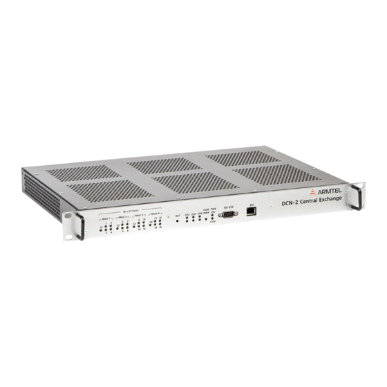
DCN-2 CENTRAL EXCHANGE User Manual 1.1.4 Design DCN-2 is designed for installation in 19" cabinet (rack). The external appearance and overall dimensions of DCN-2 are illustrated at Figure 1. Figure 1 – External appearance and overall dimensions of DCN-2 Note –The manufacturer reserves the right to change the appearance of the product without... - Page 13 DCN-2 CENTRAL EXCHANGE User Manual DCN-2 is composed of: CPU central processor; DSP switching module; 4E1 stream processing modules. The central processor controls channel switching in the switching field located on DSP module. DSP module is also used for storing and replaying the sound messages that are preloaded to its non-volatile memory.
- Page 14 DCN-2 CENTRAL EXCHANGE User Manual USB – serial interface for 4Е1 boards control; Ethernet – RJ-45 serial interface for PC communication; Kb/Mc – interface for keyboard and mouse connection; VGA – interface for display connection; DSP – signaling processor board, performs switching of speech paths, conference organization, storing and replaying of audio information;...
- Page 15 DCN-2 CENTRAL EXCHANGE User Manual The external appearance of DCN-2 with the removed enclosure cover and four installed 4E1 modules is shown in Figure 3. 1 – board 1 4E1; 2 – board 2 4E1; 3 – board 3 4E1; 4 – board 4 4E1;...
- Page 16 DCN-2 CENTRAL EXCHANGE User Manual Figure 4 shows the external appearance and overall dimensions of the board of the DSP signaling processor. Figure 4 – Board DSP 14/44 armtel.com page © Armtel info@armtel.com...
- Page 17 DCN-2 CENTRAL EXCHANGE User Manual Connectors, controls, and indications Figure 5 illustrates the fragment of the DCN-2 front panel with the соntrols. Figure 5 – Fragment of DCN-2 front panel Note – All the LEDs used on the front panel are two-colored (red/green).
- Page 18 DCN-2 CENTRAL EXCHANGE User Manual Figure 6 shows the DCN-2 rear panel with switching elements. PWR IN Fuse -48 GND 0V 16 x E1 Ports T 2A 1 – screw for connecting functional grounding; 2 – power on/off; 3 – power fuse 48 V (2A);...
-
Page 19: Marking
DCN-2 CENTRAL EXCHANGE User Manual 1.1.5 Marking A bilingual nameplate (in Russian and English) is pasted on the left side surface of the DCN-2 enclosure. The nameplate contains the following information: name, trademark, and reference information of the manufacturer;... -
Page 20: Packing
DCN-2 CENTRAL EXCHANGE User Manual 1.1.6 Packing The DCN-2 with the assembly kit and documents, which come with the supply package, is packed in a consumer package (cardboard box) according to GOST 23088-80. A label in Russian language and English language is glued onto the consumer package, said label containing the following inscriptions and symbols: ... -
Page 21: Description And Operation Of Product Components
E1 interface and for signaling alarms А1, А2. The cable is connected from one side to the back panel of DCN-2 central exchange by DIN41612 socket, while from the other side its printed board, having guides for fixing on DIN-rack 35/7,5, is mounted in a 19"... -
Page 22: Description Of Devices Connected To Unit
Redundancy module DCN-2 is designed to ensure the operability of the DCN communication system manufactured by Armtel LLC in the event of an accident in the central switch DCN-2 due to the automatic connection of the backup switch DCN-2 instead of the faulty one. -
Page 23: Multichannel Communications Recorder
PA/GA intercom systems DCN and IPN manufactured by LLC Armtel, the call of IPN group from the subscriber devices of DCN system, as well as inclusion of DCN subscriber or group into IPN call group, output calls from... -
Page 24: Digital Ats
DCN-2 CENTRAL EXCHANGE User Manual 1.3.10 Digital ATS The external digital ATS or any other device, supporting EDSS1 protocol and E1 interface (G.703/G.704). In this case, the number of DCN-16U reduces by the number of busy interfaces. 22/44 armtel.com page ©... -
Page 25: Intended Use
Preparation of DCN-2 for use is carried out by representatives of the manufacturer, or by personnel who have been trained (instructed) in the operation of products of Armtel LLC. The main preparation of the product for use is carried out during installation and connection. -
Page 26: Safety Measures When Using The Product For Its Intended Purpose
DCN-2 CENTRAL EXCHANGE User Manual 6. Carry out electrical installation and connection DCN-2 (see 2.4). 2.3 Safety measures when using the product for its intended purpose When using DCN-2 for its intended purpose, it is necessary to comply with the requirements of safety measures defined by the "Rules on Labor Protection during Operation... - Page 27 DCN-2 CENTRAL EXCHANGE User Manual 2.4.2 After installing the DCN-2 in a 19" cabinet (rack) using the fasteners included in the cabinet mounting parts, connect the electrical circuits to the switchboard in the following order: сonnect the DCN-2 connection cable outlet to the DIN41612C-96M DCN-2 plug.
-
Page 28: Operation
DCN-2 CENTRAL EXCHANGE User Manual 2.5 Operation 2.5.1 Procedure of actions of the service personnel when using the product DCN-2 requires an administrator and a duty engineer, whose functions can be distributed or combined in accordance with the organizational structure of the enterprise. -
Page 29: Product Functionality Control
DCN-2 CENTRAL EXCHANGE User Manual 2.5.4 Product functionality control Available DCN-2 indicators status depending on the mode of operation are shown in Table 4. Table 4 – Available DCN-2 indicators status (beginning) Indicator State Comment Extinguished Board is faulty Solid red... - Page 30 DCN-2 CENTRAL EXCHANGE User Manual Table 4 (end) Indicator State Comment DSP is faulty Error in the exchange of the last data set Solid red DSP2 Indicator Errors in the exchange of data sets Flashing red (lower) DSP is operational...
-
Page 31: Troubleshooting
DCN-2 CENTRAL EXCHANGE User Manual 2.5.5 Troubleshooting Possible problems and their solutions are given in Table 5. Table 5 – Troubleshooting Problem Possible Cause Solution DCN-2 is not connected to a When you turn on the Connect to the power supply... - Page 32 DCN-2 CENTRAL EXCHANGE User Manual Table 5 (end) Problem Possible Cause Solution ERR2 indicator (lower) External alarm Find the cause and fix lights red Board indicator 4E1 (S1…S4) Factory board repair (replace 4E1 board is defective off, glowing red or...
-
Page 33: Maintenance
3.1 General guidelines Maintenance shall be carried out to ensure the module’s fault-free performance and instant readiness for use. The objects of maintenance are: DCN-2 Central Exchange; Cables suitable for the product. Maintenance is performed by DCN-2 maintenance personnel. -
Page 34: Checking The Functionality Of The Product
DCN-2 CENTRAL EXCHANGE User Manual The approximate time for the technical maintenance of DCN-2 is 30 minutes. All operations performed with the unit, identified malfunctions, as well as negative results of the maintenance should be recorded in special logs. 3.4 Checking the functionality of the product The operability of the DCN-2 is checked automatically when the LED indication is turned on and checked in accordance with the instructions given in Table 4 and Table 5. -
Page 35: Repair
DCN-2 CENTRAL EXCHANGE User Manual 4 REPAIR No scheduled repair work is provided for DCN-2. Unscheduled repair shall be performed by the manufacturer at the request of the User. The place, time, procedure, and cost of the work shall be agreed upon with the manufacturer in advance. -
Page 36: Storage
DCN-2 CENTRAL EXCHANGE User Manual 5 STORAGE Conditions for storage of the DCN-2 are in the manufacturer’s individual package according to the group 1 GOST 15150-69 in heated and ventilated warehouses or air- conditioned storage facilities with a temperature range from + 5 °C to + 40 °C. -
Page 37: Transportation
DCN-2 connection cable in the DIN 41612 C-96 M connector in the cabinet to exclude its free movement. If the DCN-2 connection cable is transported as part of a communication cabinet, the DCN-2 Central Exchange is placed in a transport container without a connection cable armtel.com 35/44 page info@armtel.com... -
Page 38: Disposal
DCN-2 CENTRAL EXCHANGE User Manual 7 DISPOSAL The product is not to be disposed of together with household waste and should be delivered to a specialized center for the disposal of electronic products. The operating organization must take full responsibility for the product disposal. -
Page 39: Appendix А (Reference) Product Connection
PRODUCT CONNECTION А.1 DCN-2 connection cable DCN-2 ARMT.665200.124 cable is a part of DCN-2 Central Exchange and is designed for connection to it of Е1 digital streams (up to 16 ps.) from other switching systems. DCN-2 connection cable is a passive adapting device and is designed for use inside the telecommunication cabinet or rack, where DCN-2 is installed. - Page 40 DCN-2 CENTRAL EXCHANGE User Manual 1 – enclosure for mounting the board of DCN-2 cable on DIN-rack; 2 – the board DCN-2 connection cable; 3 – 96-contact socket of DIN41612 connector for connection to DCN-2; 4 – 50-core cable; Х4, Х5 - terminal blocks; Х8…Х23 – RJ-45 sockets for connection of E1 digital stream cables (designation on the board «Port 1»...
- Page 41 DCN-2 CENTRAL EXCHANGE User Manual The external appearance of any of 16 sockets of RJ-45 socket for DCN-2 connection cable with contact numbering is illustrated at Figure А.2. Figure А.2 – Socket RJ-45 Connection to the central exchange of E1 digital stream cables is executed by the external cables: either with RJ-45 sockets to 16 Х8…Х23 sockets (indicated on the board as...
- Page 42 DCN-2 CENTRAL EXCHANGE User Manual The function of contacts for Х4 socket is given in Table А.2. Table А.2 - Assignment of connector contacts Х4 Contact Signal Function Contact Signal Function Rx a1 Receipt 1 Port1 Rx a5 Receipt 1 Port5...
- Page 43 DCN-2 CENTRAL EXCHANGE User Manual The function of contacts for Х5 socket is given in Table А.3. Table А.3 - Assignment of connector contacts Х5 Contact Signal Function Contact Signal Function Rx a9 Receipt 1 Port9 Rx a13 Receipt 1 Port13...
- Page 44 DCN-2 CENTRAL EXCHANGE User Manual DCN-2 cable has the input («Alarm in») and output Alarm out») of alarm signaling. «Alarm in» input is Х6 socket designed for connection of galvanically isolated relay contacts from other devices (for example, the fuse boards, having such outputs), by which the alarm signals from other devices of the communication system are transferred to DCN-2.
-
Page 45: А.2 Power Supply Cable
DCN-2 CENTRAL EXCHANGE User Manual А.2 Power supply cable The power supply cable is connected to the plug of the «-48 GND 0V» connector (see Figure 6), then to the power supply source. The external appearance of the supply cable socket with the contact numbering is illustrated in Figure А.3. - Page 46 DCN-2 CENTRAL EXCHANGE User Manual FOR NOTES 44/44 armtel.com page © Armtel info@armtel.com...
- Page 47 © Armtel...
- Page 48 ООО «АРМТЕЛ» Телефон/факс: +7 (812) 703-41-11 www.armtel.com | info@armtel.com Юридический и фактический адрес: Россия, 192012, Санкт-Петербург, Запорожская ул., д.12, строение 1, офис 1/2 ТЕХНИЧЕСКАЯ ПОДДЕРЖКА 8-800-500-90-17 (для звонков из России) +7-812-633-04-02 (для международных звонков) support@armtel.com ДОПОЛНИТЕЛЬНАЯ ИНФОРМАЦИЯ ПО ПРОДУКТУ РАЗМЕЩЕНА НА...
Need help?
Do you have a question about the DCN-2 Central Exchange and is the answer not in the manual?
Questions and answers