
Subscribe to Our Youtube Channel
Related Manuals for ARMTEL DCN-16U


Summary of Contents for ARMTEL DCN-16U
- Page 1 DCN-16U Exchange (basic version, version with pre-installed switching module DCN-Q4E) ARMT.665200.001UM User Manual Document version 17-11 26.30.11.190 2020...
- Page 2 © Armtel info@armtel.com...
-
Page 3: Introduction
ARMT.665200.001-01 with pre-installed switching processor module DCN-Q4E (4xE1) ARMT.665200.010 to the User. DCN-16U exchange is a compact connection unit for subscriber equipment within the DCN distributed of Public Address and General Alarm system. Short product name – DCN-16U. -
Page 4: Safety Provisions
(BASIC VERSION, VERSION WITH PRE-INSTALLED SWITCHING MODULE DCN-Q4E) User Manual SAFETY PROVISIONS During installation and operation of DCN-16U, observe safety precautions laid out in local regulations on electrical safety. To avoid electric shock, do not: − operate the product if its case is not connected to the ground rod;... -
Page 5: Table Of Contents
1.2.4 DCN-16U subscribers connection cable ....................17 1.3 Subscriber units connected to DCN-16U (with DCN-Q4E) ..............18 1.3.1 General information ............................ 18 1.3.2 DCN-2 Exchange / DCN-Q4E switching processor module (to DCN-16U with DCN-Q4E) .................................. 18 1.3.2 Digital ATX (to DCN-16U with DCN-Q4E) ..................18 1.3.3 Subscriber units ............................ - Page 6 7 DISPOSAL ................................... 34 ANNEX А (reference) Сonnecting optional equipment and power supply ..........35 А.1 DCN-Q4E E1 connection cable ........................35 А.2 DCN-16U digital subscribers connection cable ..................38 А.3 Connection to power supply ..........................41 А.4 Phantom power supply ............................42 page 4/44 armtel.com...
-
Page 7: Description And Operation
Therefore, maximum capacity of DCN-Q4E-based system can be up to 60 subscribers. The switching processor module DCN-Q4E intended for use as central exchange unit of DCN system, at the enterprise of industry and transport. DCN system (Armtel LLC) built with product provide simplex communication between loud-speaking subscriber devices manufactured by Armtel LLC, duplex communication with telephony subscribers, paging, and emergency loud warning. - Page 8 Armtel subscriber units, an expanded sound transmit frequency band of 6.8 kHz is used. DCN-16U is connected to a central exchange of DCN system by E1 line, which is used for transmitting voice traffic channels and signaling between the central exchange and subscriber units.
-
Page 9: Main Specifications
DCN-16U Exchange is ready for operation as supplied and no programming is required during operation except for assignment of subscriber unit connection ports. Operation of DCN-16U Exchange and subscriber units connected to it is managed by a central exchange of DCN system connected to DCN-16U via E1 line. - Page 10 − I.432 of recommendations of ITU-T (ISDN standard) – User-network interface B- ISDN – physical level specification; − DSS1 – subscriber signaling protocol. Main specifications and performance characteristics of DCN-16U Exchange are given in the Table 1. page 8/44 armtel.com ©...
- Page 11 Conditioned locations or partially conditioned air. The product enables/disables the configured subscriber units without power shutdown and reboot. DCN-16U has protection against incorrect polarity of power supply connection. ATTENTION: WHEN CONNECTING PHANTOM POWER ADHERENCE TO INSTRUCTIONS OF MANUALS FOR CONNECTED SUBSCRIBER UNITS IS SCTRICTLY...
-
Page 12: Scope Of Supply
DCN-16U EXCHANGE (BASIC VERSION, VERSION WITH PRE-INSTALLED SWITCHING MODULE DCN-Q4E) User Manual 1.1.3 Scope of supply Scope of supply for DCN-16U is given in the Table 2. Table 2 – Scope of supply Quantity, Identification Name Note pcs. ARMT.665200.001* DCN-16U Exchange Additional information on scope of supply ARMT.665200.102... -
Page 13: Design
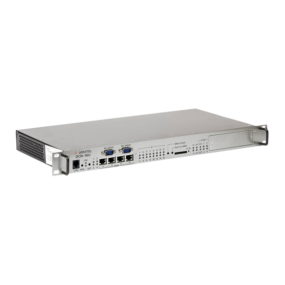
Figure 2. Figure 2 - DCN-16U external and overall dimensions Front panel of DCN-16U with pre-installed DCN-Q4E module and connector and LED indicators is shown in the Figure 3 . Figure 3 – DCN-16U Front panel Note –... - Page 14 К1, К2 error relays; − FUSЕ – group of indicators of fuse state: − SYS – status indicator of DCN-16U Main system fuse, installed in main supply voltage circuit 48 V; − EXT – external failure source status indicator;...
- Page 15 DCN-16U EXCHANGE (BASIC VERSION, VERSION WITH PRE-INSTALLED SWITCHING MODULE DCN-Q4E) User Manual Back panel of DCN-16U with connectors and fuses is shown in the Figure 5. Figure 5 – DCN-16U Back panel DCN-16U Back panel contains: terminals for DCN-16U case grounding;...
-
Page 16: Product Components Description And Operation
1.2 Product components description and operation 1.2.1 General DCN-16U components are as follows: − DCN-Q4E switching processor module (only in DCN-16U with DCN-Q4E module); − DCN-Q4Е E1 connection cable (only in DCN-16U with DCN-Q4E module); − DCN-16U subscribers connection cable. - Page 17 ISDN – physical level specification; − DSS1 – subscriber signaling protocol. In terms of design DCN-Q4E module being a part of DCN-16U Exchange is a printed circuit board to be enclosed into DCN-16U exchange, and powered from its main board. E1 line is connected through DRB-25FA socket on the back panel of the module by means of special cable.
-
Page 18: Dcn-Q4E E1 Connection Cable
DCN-Q4Е E1 connection cable is intended for connection to DCN-Q4E switching processor module being a part of DCN-16U exchange, up to four DCN-type exchange units. In addition, it enables to connect digital Exchanges (or other products) by digital E1 lines, but the number of DCN exchanges connected decreases to the number of such products. -
Page 19: Dcn-16U Subscribers Connection Cable
E1 lines, external error message signal and generating А1, А2 failure signals. The cable is connected to DCN-16U Exchange Back panel through C type DIN41612 socket from one end and from another end it is mounted into 19-inch rack (cabinet) by means of printed circuit board with guides for clamping on DIN-rail 35/7.5. -
Page 20: Subscriber Units Connected To Dcn-16U (With Dcn-Q4E)
Ones have unified software but different capacities and design. 1.3.2 Digital Exchange (to DCN-16U with DCN-Q4E) External digital Exchange or other device supporting EDSS1 protocol and E1 interface (G.703/G.704). In this case, the number of DCN-16U is reduced by the number of busy interfaces. 1.3.3 Subscriber units... - Page 21 DCN-16U EXCHANGE (BASIC VERSION, VERSION WITH PRE-INSTALLED SWITCHING MODULE DCN-Q4E) User Manual DIS call station is manufactured as a desktop version only, DIS-TOP call station can be desktop, wall-mounted and flush-mounted. Depending on version call stations can be additionally equipped with the external...
- Page 22 DCN-16U EXCHANGE (BASIC VERSION, VERSION WITH PRE-INSTALLED SWITCHING MODULE DCN-Q4E) User Manual to the control line to activate any given functions of the central exchange, for example, to start announcement transmission. The module allows for using analogue call stations (for example, the ones made by Neumann Elektronik: WFA, WFAEx, WFK) incorporated into the communication system.
-
Page 23: Intended Use
Table 1. 2.1.2 It is forbidden to supply phantom power to products connected to DCN-16U at the same time as main power is supplied to them. 2.1.3 The requirements for operating conditions and the choice of the place of installation given in this document take into account the most typical factors that affect the operation of DCN-16U. -
Page 24: Safety Precautions
(BASIC VERSION, VERSION WITH PRE-INSTALLED SWITCHING MODULE DCN-Q4E) User Manual 2.3 Safety precautions During installation and operation of DCN-16U, observe safety precautions laid out in local regulations on electrical safety. To avoid electric shock, do not: − operate the product if its case is not connected to the ground rod;... -
Page 25: Installation, Connection And Dismantling
(BASIC VERSION, VERSION WITH PRE-INSTALLED SWITCHING MODULE DCN-Q4E) User Manual 2.4 Installation, connection and dismantling 2.4.1 Once DCN-16U installed in 19-inch rack (cabinet) using clamps included in scope of supply of rack (cabinet) clamping elements, it should be connected to a patch bay in the following order: −... -
Page 26: Operation
− Place DCN-16U in consumer packaging. 2.5 Operation 2.5.1 Product On/Off The product is turned on by connecting the voltage of power source to DCN-16U power socket. After initialization DCN-16U functions as follows: − Provides for communication between subscribers according to configuration data;... -
Page 27: Product General Performance Monitoring Routine
(BASIC VERSION, VERSION WITH PRE-INSTALLED SWITCHING MODULE DCN-Q4E) User Manual 2.5.2 Product general performance monitoring routine Possible states of DCN-16U indicators depending of operation mode are given in Table 3. Table 3 - Possible states of DCN-16U indicators depending of operation mode Indicator... - Page 28 DCN-16U EXCHANGE (BASIC VERSION, VERSION WITH PRE-INSTALLED SWITCHING MODULE DCN-Q4E) User Manual Table 3 - Possible states of DCN-16U (with DCN-Q4E) indicators depending of operation mode (continuous) Indicator State Comment DCN-16U Port is not engaged in configuration Port is engaged in configuration, but first...
- Page 29 DCN-16U EXCHANGE (BASIC VERSION, VERSION WITH PRE-INSTALLED SWITCHING MODULE DCN-Q4E) User Manual Table 3 - Possible states of DCN-16U indicators depending of operation mode (end) Indicator State Comment DCN-16U Fuse of phantom power of subscriber units Continuously shine green PoU 5-8 connected to 5-8 channels is OK...
-
Page 30: Troubleshooting
DCN-16U don’t glow operability Find the cause, remove the At power on, SYS fuse (48 V) DCN-16U main fuse went cause of trouble and change indicator is red main fuse of DCN-16U Fuse of phantom power supply Find the cause, remove the... - Page 31 Subscriber unit connection Change subscriber unit cable is broken connection cable Runtime program loading mode At startup, CPU 1 doesn’t Turn DCN-16U off and on glow CPU didn’t start Load DCN-16U configuration Software is not loaded At startup, CPU 1 is red...
-
Page 32: Maintenance
− Remove dust and dirt from product surface. − Check product mounting in the cabinet (rack) and external sockets clampings. − Inspect cables attaching to DCN-16U (it should not be squeezed and damaged). − Check reliability of connection to cable connectors – cables should not be tensed. -
Page 33: Repair
User Manual 4 REPAIR No scheduled repair work is provided for DCN-16U. Unscheduled repair shall be performed by manufacturer at the request of the User. The place, time, procedure and cost of the work shall be agreed with the manufacturer in advance. -
Page 34: Storage
(BASIC VERSION, VERSION WITH PRE-INSTALLED SWITCHING MODULE DCN-Q4E) User Manual 5 STORAGE DCN-16U storage conditions are as follows: in item-specific manufacturer’s packaging, heated and ventilated storages or warehouses with air-conditioning with a range of temperature from plus 5 to plus 40 °С. -
Page 35: Transportation
− the shipping container on the shipping vehicle is fastened to avoid falling and collision. At the same time, transportation of the DCN-16U connection cable and DCN-Q4E E1 connection cable installed in the rack on a DIN-rai is allowed as part of the rack. Measures must be taken to secure the DCN-16 connection cable and the D-SUB-25A connector of the DCN-Q4E E1 connection cable to prevent their free movement. -
Page 36: Disposal
DCN-16U EXCHANGE (BASIC VERSION, VERSION WITH PRE-INSTALLED SWITCHING MODULE DCN-Q4E) User Manual 7 DISPOSAL The product is not subject to disposal along with daily waste and shall be delivered to a special electronic product disposal facility. Operator is responsible for product disposal. -
Page 37: Annex А (Reference) Сonnecting Optional Equipment And Power Supply
DCN-16U EXCHANGE (BASIC VERSION, VERSION WITH PRE-INSTALLED SWITCHING MODULE DCN-Q4E) User Manual ANNEX А (REFERENCE) СONNECTING OPTIONAL EQUIPMENT AND POWER SUPPLY А.1 DCN-Q4E E1 connection cable DCN-Q4Е E1 connection cable with overall dimensions is illustrated at Figure А.1. Cable weight is (0,31 ± 0,05) kg. - Page 38 DCN-16U EXCHANGE (BASIC VERSION, VERSION WITH PRE-INSTALLED SWITCHING MODULE DCN-Q4E) User Manual Table А.2 – X1 terminal box and RJ-45 pin assignment RJ-45 Socket contact Terminal box contact Signal Assignment Tx 1 Transmission 1 Rx 1 Reception 1 Rx 2...
- Page 39 User Manual − The subscriber unit is not available for DCN-Q4E (line break, unit is faulted/out); − DCN-16U, which connected by E1 line to DCN-Q4E, is not available (line break, DCN-16U is faulted/out); − Other devices, which connected by E1 line to DCN-Q4E, is not available (line break, device is faulted/out).
-
Page 40: А.2 Dcn-16U Digital Subscribers Connection Cable
Sys signals generation; 5 – ХТ5 terminal ship for A2 failure signal generation. Figure А.3 – DCN-16U subscribers connection cable DCN-16U subscriber connection cable is connected to DCN-16U exchange back panel through C type DIN41612 socket from one end and from another end it is mounted into 19- inch rack (cabinet) by means of printed circuit board with guides for clamping on DIN-rail 35/7.5. - Page 41 DCN-16U EXCHANGE (BASIC VERSION, VERSION WITH PRE-INSTALLED SWITCHING MODULE DCN-Q4E) User Manual Table A.1 – Terminal assignment of XT1 Contact Assignment Contact Assignment Ua1+ Ua9+ Subscriber interface line 1 Subscriber interface line 9 Ub1- Ub9- Ua2+ Ua10+ Subscriber interface line 2...
- Page 42 DCN-16U EXCHANGE (BASIC VERSION, VERSION WITH PRE-INSTALLED SWITCHING MODULE DCN-Q4E) User Manual Terminal assignment of ХT2 is given in the Table A.2. Table A.2 – Terminal assignment of XT2 Contact Assignment Contact Assignment TXb1 TXb3 First Е1 line, transmission Third Е1 line, transmission...
-
Page 43: А.3 Connection To Power Supply
User Manual А.3 Connection to power supply First the power cable connects to the “-48 0V GND” socket of DCN-16U (refer to Figure 5), after – to a power source. Power cable socket with pin numbers is shown in the Figure A.4. -
Page 44: А.4 Phantom Power Supply
3 “GND” of power socket (refer to Figure A.4) and place the jumpers on the contact pairs that corresponds to subscriber units (refer to Figure A.5) 1 – DCN-16U power cable socket; 2 – contact pairs for installation of jumpers 1…16 Ub-; 3 – contact pairs for installation of jampers 1…16 Uа+. - Page 45 DCN-16U EXCHANGE (BASIC VERSION, VERSION WITH PRE-INSTALLED SWITCHING MODULE DCN-Q4E) User Manual NOTES armtel.com page 43/44 info@armtel.com © Armtel...
- Page 46 DCN-16U EXCHANGE (BASIC VERSION, VERSION WITH PRE-INSTALLED SWITCHING MODULE DCN-Q4E) User Manual page 44/44 armtel.com © Armtel info@armtel.com...
- Page 47 © Armtel...
- Page 48 ARMTEL LLC Tel./fax: +7 (812) 703-41-11 www.armtel.com | info@armtel.com Legal and physical address: 12 buildung 1, Zaporozhskaya street, office 1/2, Saint Petersburg, 192012 TECHNICAL SUPPORT 8-800-500-90-17 (for calls from Russian Federation) +7-812-633-04-02 (for international calls) support@armtel.com MORE INFORMATION ABOUT PRODUCT ON OFFICIAL SITE...
Need help?
Do you have a question about the DCN-16U and is the answer not in the manual?
Questions and answers