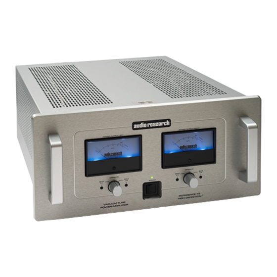
Advertisement
Quick Links
PROCEDURE NUMBER
REF75SE Update
ISSUED:
3/20/2015
Title:
REF75SE
Update Procedure
Caution Electrical Shock Hazard:
To prevent electrical shock make sure the AC POWER CORD IS NOT CONNECTED TO
THE REF75
DO NOT touch the Vacuum Tube Socket Pins when inserting or removing the vacuum
tubes, as there may be hazardous voltages present even after the REF75 has been
switched "Off" for a period of time.
If the REF75 has been "ON", allow the Hot Vacuum Tubes to cool first before removing.
Advertisement

Summary of Contents for Audio Research REF75SE
- Page 1 PROCEDURE NUMBER REF75SE Update ISSUED: 3/20/2015 Title: REF75SE Update Procedure Caution Electrical Shock Hazard: To prevent electrical shock make sure the AC POWER CORD IS NOT CONNECTED TO THE REF75 DO NOT touch the Vacuum Tube Socket Pins when inserting or removing the vacuum tubes, as there may be hazardous voltages present even after the REF75 has been switched “Off”...
- Page 2 3/20/2015 PURPOSE The purpose of this document is to define the process for updating the REF75 Amplifier to a REF75SE Amplifier. SCOPE This document specifies materials, equipment, and assembly instruction and safety precaution requirements for assembling the SE Update Kit.
- Page 3 PAGE: 2 of 11 PROCEDURE FOR: REF75SE Update ISSUED: 3/20/2015 4.0. PROCEDURE 4.1. Panel and Input Wire Removal Remove 18 – #6 Screws that secure the Top Cover to the Chassis. 4.1.1. 4.1.2. Remove Top Cover. 4.1.3. Discharge the Power Supply!!
- Page 4 PAGE: 3 of 11 PROCEDURE FOR: REF75SE Update ISSUED: 3/20/2015 Figure 3 Tip used for Tip used for resistor install Component removal Figure 4...
- Page 5 PAGE: 4 of 11 PROCEDURE FOR: REF75SE Update ISSUED: 3/20/2015 4.2. IEC Update 4.2.1. Loosen the two terminal screws on the IEC that hold the Blue and Brown wires. Remove 2 – Screws that secure the IEC to the Chassis.
- Page 6 PAGE: 5 of 11 PROCEDURE FOR: REF75SE Update ISSUED: 3/20/2015 Figure 5 Figure 6 Figure 7 Figure 8 Figure 9...
- Page 7 PAGE: 6 of 11 PROCEDURE FOR: REF75SE Update ISSUED: 3/20/2015 4.2. Resistor Replacement Remove 4 – 1- 1.0Ù 2W Resistors (outlined in Figure 10) and replace with 4 - 1.0Ù 4.2.1. 3W Resistors from the update kit. *Reuse the containment sleeves from the removed resistors on the new ones.
- Page 8 PAGE: 7 of 11 PROCEDURE FOR: REF75SE Update ISSUED: 3/20/2015 4.3. Diode Replacement Remove the 4 – Diodes from the main board and replace with the 4 – High Speed 4.3.1. Diodes (30506700) from the update kit. *When removing the old diodes, start by removing the lead closest to the capacitor bank first, followed by the lead near the edge of the board;...
- Page 9 PAGE: 8 of 11 PROCEDURE FOR: REF75SE Update ISSUED: 3/20/2015 4.4. Mainboard Hex Spacer Replacement Place masking tape over 6 – Screws on the bottom of the chassis that secure the Hex 4.4.1. Spacers. *The other 2 – Screws are partially under the feet, so they won’t fall out when removing spacers! Remove 1 –...
- Page 10 PAGE: 9 of 11 PROCEDURE FOR: REF75SE Update ISSUED: 3/20/2015 4.5. Input Wires and Panel *Make sure the following wires are through the through hole before soldering and when soldering use extreme caution not to melt and damage the wire insulation! Repeat Steps 4.5.1 –...
- Page 11 PAGE: 10 of 11 PROCEDURE FOR: REF75SE Update ISSUED: 3/20/2015 Figure 22 Place 4 – KT150 Tubes into the sockets and 2 – 6H30P Tubes in the other sockets, 4.5.5. place 2 – Damping Tubes around both 6H30P Tubes. Refer to Figure 23 and Figure 24...
- Page 12 PAGE: 11 of 11 PROCEDURE FOR: REF75SE Update ISSUED: 3/20/2015 Figure 24 *Refer to the old 6H30P Tubes for tube damper placement! Place the Top Cover on the chassis and secure with the 18 – #6 Screws removed in 4.5.6.


Need help?
Do you have a question about the REF75SE and is the answer not in the manual?
Questions and answers