
Subscribe to Our Youtube Channel
Related Manuals for IPS Controllers M720


Summary of Contents for IPS Controllers M720
- Page 1 M720 pH/ORP Controller ipscontrollers.com Dose Dose Alert Alert IPS-M720 Dose Delay Down Level Time Time Auto Flow MODE AC Power Flow Owner’s Manual...
-
Page 2: Table Of Contents
Table of Contents I. Introducti on page 2 A. Water Chemistry page 2 B. Safety page 3 C. System Components page 4 D. Specifi cati ons page 7 E. Controller Panel Descripti ons page 8 F. Electrical Descripti ons page 10 II. -
Page 3: Introducti
M720 pH/ORP Controller Owner’s Manual I. Introduction A. Water Chemistry Water chemistry is a complex science that contains many variables. These variables not only affect the water environment itself, but they can have adverse effects on your equipment as well as your health. -
Page 4: Safety
M720 pH/ORP Controller Owner’s Manual IMPORTANT SAFETY INSTRUCTIONS READ AND FOLLOW ALL INSTRUCTIONS 2. Risk of electric shock: Connect the controller to a dedicated ground-fault circuit interrupter (GFCI) circuit breaker. 3. Disconnect power before servicing the controller. 4. Inspect all power cords frequently. Any damaged cords should be replaced immediately to reduce the risk of injury by shock. -
Page 5: System Components
2. Flow Cell with Flow Switch a. An injection-molded flow cell with integrated flow-switch houses the pH and ORP sensors, and partners with the M720 controller to monitor the pH and ORP levels in the water. - Page 6 (flow light should turn off). 3. pH and ORP Sensors a. pH Sensor – standard (Use only IPS Controllers part # SXPH to maintain NSF Certification) b. ORP Platinum Sensor – standard (Use only IPS Controllers part # SXORP to maintain NSF Certification) c.
- Page 7 M720 pH/ORP Controller Owner’s Manual...
-
Page 8: Specifications
M720 pH/ORP Controller Owner’s Manual D. Specifications Enclosure: 6.375”L x 4.75”W x 3.5”D (Note: Mounting board dimensions are 16”L x 12”W x 0.25”D) Electrical Input/Output: 110/230 VAC, 50 - 60 Hz pH Set Level: 7.0 to 8.0 ORP Set Level: 400 mV to 900 mV Dose Time: Off, Continuous, or Timed cycle High Alert: pH default of 8.0, ORP default of 900... -
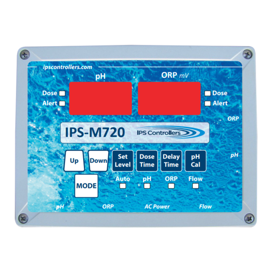
Page 9: Controller Panel Descripti Ons
Flow Controller Communication digital display Electrical pushbutton LEDs Figure 2: M720 Controller Components Connecti ons E. Controller Panel Descripti ons 1. Digital Displays and Functi on LEDs a. pH 1. Alert - red LED 2. Dose - green LED b. ORP 1. - Page 10 M720 pH/ORP Controller Owner’s Manual 2. Mode - pushbutton adjustments a. Auto - red LED b. pH standby - green LED c. ORP standby - yellow LED d. OFF mode - In standby, press and hold Mode button for 3 seconds to turn controller off.
-
Page 11: Electrical Descripti Ons
M720 pH/ORP Controller Owner’s Manual F. Electrical Descripti ons 1. Power a. 110/230 VAC, 50-60 Hz, 3-wire grounded NEMA 5 power cord. GFCI source required. 2. Dip Switches (1-4) a. 1: pH/ORP interlock (default: OFF) No ORP feed if pH is feeding (ON). -
Page 12: Installati
Note: The controller and flow cell are factory mounted to the ABS board for convenience. a. Securely mount ABS mounting board with M720 controller and flow cell on wall (vertical installation). b. If applicable, securely attach the peristaltic pump with the... - Page 13 Note: Carefully unpack the pH and ORP sensors and set aside in a clear area until ready to install into the flow cell. a. Verify that the M720 controller power is OFF. b. Carefully remove the plastic protective caps from the sensors and store in a separate location for future re-use.
- Page 14 M720 pH/ORP Controller Owner’s Manual 4. Electrical Connections (Should be completed by a licensed Electrician) a. Verify that the M720 controller power is OFF. b. Connect the pH feeder connection to the appropriate peristaltic pump or other device. c. Connect the ORP feeder connection to the appropriate peristaltic pump or other device.
-
Page 15: Operati
III. Operation A. Startup and Shutdown 1. Startup a. Plug M720 power cord into power outlet. For outdoor installations, ensure the use of a watertight outlet cover. b. Turn on the filter pump and verify the water flow through the flow cell by opening the sample port valve (center) and observing a steady stream of water. -
Page 16: Modes And Adjustments
The green Flow LED will be illuminated if water is flowing through the flow cell. B. Modes and Adjustments 1. Auto a. This is the normal operational mode of the M720 controller. b. The controller allows full operation and monitoring of both pH and ORP levels. - Page 17 M720 pH/ORP Controller Owner’s Manual 2. pH standby Note: While in this mode, the green pH standby LED will illuminate, both the pH and ORP digital displays will show dashes, and all Auto functions will be disabled. When a function pushbutton is pressed, the corresponding digital display will show the function.
- Page 18 M720 pH/ORP Controller Owner’s Manual iii. Use Up/Down button to increase/decrease Over Timer iv. When finished, press Mode button to continue 4. The Over Timer is interlocked with the Dose Time selection. i. If the Dose Time is set to a timed cycle, the Over Timer will count timed feed cycles.
- Page 19 M720 pH/ORP Controller Owner’s Manual iv. Use Up/Down button to increase/decrease pH High Alert v. When finished, press Mode button to continue Low Alert 1. Default: 7.0 pH 2. Selectable range: OFF, 6.8 pH to 7.4 pH (acid feed). A...
- Page 20 M720 pH/ORP Controller Owner’s Manual 4. ORP standby Note: While in this mode, the yellow ORP standby LED will illuminate, both the pH and ORP digital displays will show dashes, and all Auto functions will be disabled. When a function pushbutton is pressed, the digital display will show the function.
- Page 21 M720 pH/ORP Controller Owner’s Manual ii. Press and hold Mode button and then press Delay Time button (red ORP alert LED will come on) release both buttons. You are now in Set Over Timer mode. iii. Use Up/Down buttons to increase/decrease Over Timer iv.
- Page 22 M720 pH/ORP Controller Owner’s Manual ii. Press and hold Mode button and then press Set Level button (red ORP alert LED will come on) release both buttons. You are now in Set Alerts mode. iii. Press Set Level button again to display current High Alert iv.
- Page 23 M720 pH/ORP Controller Owner’s Manual b. The fl ow switch must be installed for safety reasons to prevent dosing chemicals when there is no fl ow in the circulati on piping. Figure 4: Flow Switch Jumper 6. Factory defaults To return the controller to the factory defaults: a.
-
Page 24: Maintenance
M720 pH/ORP Controller Owner’s Manual C. Maintenance 1. Winterizing (extended shutdowns or colder climates) a. Turn off the M720 controller and shut off main power to controller. b. Gently remove the ph and ORP sensors from the flow cell. Fill the provided protective caps (removed during installation) with water and re-install onto each sensor, and store in a warm, secure location. - Page 25 M720 pH/ORP Controller Owner’s Manual h. Turn on the M720 controller. Open the flow cell valves and wait for a few minutes for the system to stabilize and get an accurate reading. Adjust the Set Level if necessary. If the sensor does not show the indicated readings, then it...
-
Page 26: Troubleshooting
M720 pH/ORP Controller Owner’s Manual Troubleshooting A. pH level too low or Alert LED on 1. pH Set level is too low: Check pH level with test kit and adjust Set Level as necessary. 2. Chemical dose time too high: Lower dose time. - Page 27 M720 pH/ORP Controller Owner’s Manual if using timed feed, or switch to continuous feed if using a salt chlorine generator. 4. Chemical dose time too low: Increase the dose time. 5. Chemical feeder is empty: Refill the feeder. 6. Chemical check valve/injector is clogged: Switch acid feed tube to chlorine injector to clean.
- Page 28 M720 pH/ORP Controller Owner’s Manual 2. Inadequate Flow: Check flow through flow cell and controller. 3. Blown output fuse in the controller: Replace fuse. G. Flow LED off 1. Verify that all appropriate valves are open. 2. Verify that there is sufficient pressure in the line. Close right side valve slightly if necessary.
-
Page 29: Warranty
M720 pH/ORP Controller Owner’s Manual Warranty IPS-M720 pH/ORP Controllers IPS Controllers warrants the IPS-M720 controller to be free of defects in materials and workmanship for a period of five (5) years from the date of installation. This warranty is limited to the repair or replacement of defective components (at our discretion) when returned to the factory within the five (5) year warranty period. - Page 30 Factory Contact: 30826 Wealth Street, Murrieta, CA 92563 phone. 877-693-6903, fax. 951-693-3224 web. www.ipscontrollers.com M720OM 01/22...
Need help?
Do you have a question about the M720 and is the answer not in the manual?
Questions and answers